A figure 2-6, Dgc-2020 – Basler Electric DGC-2020 Manuel d'utilisation
Page 71
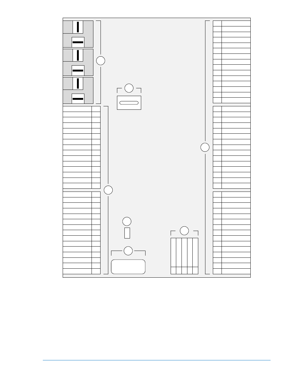
Figure 2-6. Panneau arrière du contrôleur DGC-2020, version de matériel 3
DGC-2020
CHASSIS
BATT –
BATT +
RDPBATT +
RDPBATT –
RDPTXD –
RDPTXD +
OIL
FUEL
COOLANT
SENDER COM
485 SHIELD
485 B
485 A
INPUT 16
1
2
3
4
5
6
7
8
9
10
11
12
13
14
15
INPUT 15
INPUT 14
INPUT 13
INPUT 12
INPUT 11
INPUT 10
INPUT 9
INPUT 8
INPUT 7
INPUT 6
INPUT 5
INPUT 4
INPUT 3
INPUT 2
INPUT 1
16
17
18
19
20
21
22
23
24
25
26
27
28
29
30
MPU +
MPU –
Not Used
Not Used
GEN VN
Not Used
GEN VC
Not Used
GEN VB
Not Used
GEN VA
Not Used
BUS VB
Not Used
BUS VA
31
32
33
34
35
36
37
38
39
40
41
42
43
44
45
OUT 8
OUT 9
COM 10, 11, 12
OUT 10
OUT 11
OUT 12
Not Used
IA –
IA +
Not Used
IB –
IB +
Not Used
IC –
IC +
61
62
63
64
65
66
67
68
69
70
71
72
73
74
75
E STOP
E STOP
CAN L
CAN H
SHIELD
COM 1, 2, 3
OUT 1
OUT 2
OUT 3
COM 4, 5, 6
OUT 4
OUT 5
OUT 6
COM 7, 8, 9
OUT 7
46
47
48
49
50
51
52
53
54
55
56
57
58
59
60
P0067-67
B
B
A
START
RUN
PRE
C
D
E
BUS VA
Not Used
BUS VB
Not Used
BUS VC
76
77
78
79
80
B
9400270990 Rev X
DGC-2020 – Interface HMI
2-29