Figure 6-16, E 6-26, Dgc-2020 – Basler Electric DGC-2020 Manuel d'utilisation
Page 324: Lo a d
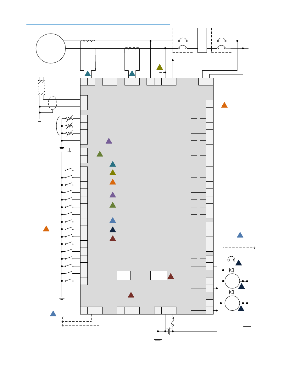
Connexion monophasée A-C pour des applications typiques
Figure 6-16. Connexion monophasée A-C pour des applications typiques
31
32
MPU+
MPU–
69
IA
–
68
IA
+
72
IB
–
71
IB
+
75
IC
–
74
IC
+
41
GEN VA
39
GEN VB
37
GEN VC
35
GEN VN
45
BUS VA
43
BUS VB
A
C
N
51
52
OUT 1
53
54
55
56
57
58
59
60
61
62
63
64
65
66
OUT 2
OUT 3
OUT 4
OUT 5
OUT 6
OUT 7
OUT 8
OUT 9
OUT 10
OUT 11
OUT 12
PRE
RUN
START
START
SOLENOID
FUEL
SOLENOID
2
BATT
–
3
BATT
+
1
CHASSIS
GLOW PLUGS
8
9
OIL
FUEL
10
11
COOLANT
SENDER COM
46
47
ESTOP
ESTOP
15
16
INPUT 16
17
18
19
20
21
22
23
24
25
26
27
28
29
30
INPUT 15
INPUT 14
INPUT 13
INPUT 12
INPUT 11
INPUT 10
INPUT 8
INPUT 9
INPUT 7
INPUT 6
INPUT 5
INPUT 3
INPUT 4
INPUT 2
INPUT 1
6
RDP BATT–
7
RDP BATT+
Horn
Not in Auto
Global Alarm
Global Pre-Alarm
Open Generator Breaker
Close Generator Breaker
Open Mains Breaker
Close Mains Breaker
Governor Raise
Governor Lower
AVR Raise
AVR Lower
Emergency
Stop
Mains Bkr Status
Gen Bkr Status
Close Mains Breaker
Open Mains Breaker
Close Gen Breaker
Open Gen Breaker
P0071-39
M
P
U
GEN CKT
BKR
L1
L3
N
Mechanical
Senders
12/24V
5
RDP TXD–
4
RDP TXD+
Mini-B
USB
Modem
13
485
B
14
485
A
12
485
SHIELD
49
CAN H
50
SHIELD
48
CAN L
3
3
8
8
1
1
4
5
DGC-2020
3
Labels indicate the functions assigned by
the default programmable logic to the
contact inputs and output contacts.
1
Current inputs are 1A or 5A, depending
on style.
4
Connect near engine block (negative
battery terminal) side of senders.
5
Jumper terminals 46 and 47 if not using
an emergency stop switch. See
Emergency Stop Input section for
optional wiring methods.
8
Optional. Refer to style number for
ordering information.
MAINS CKT
BKR
L
O
A
D
To ECU
CAN Bus
To ECU Power
Or Key-on Terminal
6
7
Connect to ECU on ECU equipped
engines only.
If component is under ECU control, do
not connect to DGC-2020.
6
6
7
7
7
2
Optional. Jumper terminals 39 and 37.
2
GENERATOR
≤ 480V
6-26
Installation du contrôleur DGC-2020
9400270990 Rev X