Multi-Contact MA213 Manuel d'utilisation
Page 6
Advanced Contact Technology
6 / 16
www.multi-contact.com
4
5
6
7
8
9
10
11
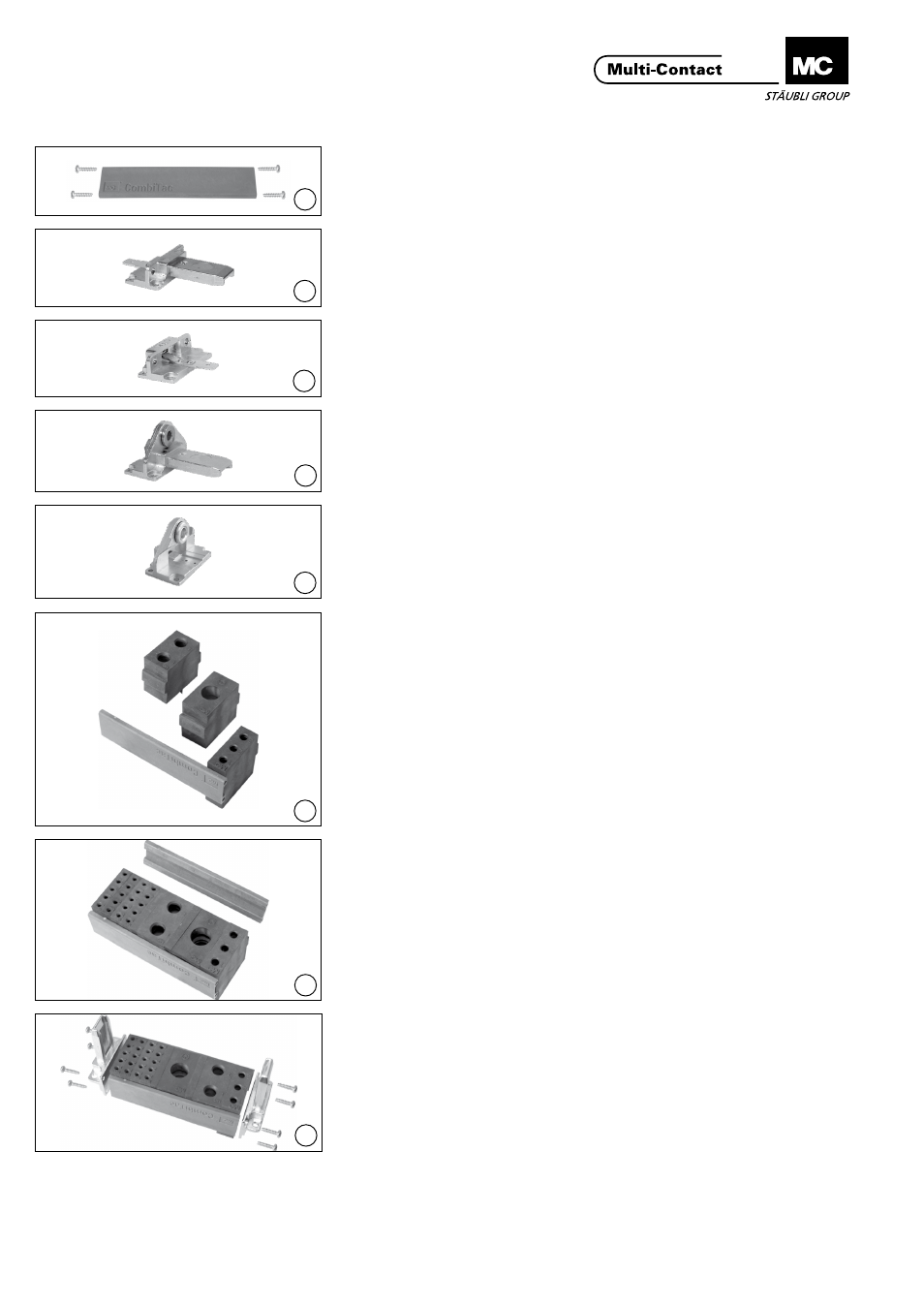
Montage des supports de
contacts
Assembly of the contact
carrier
Pièces détachées
Individual parts
(ill. 4)
Rail de fixation avec vis à tôle à tête
cylindrique bombée
(ill. 4)
Supporting rail with cross recessed
screws
(ill. 5)
Terminaison pour boîtier, broches
(ill. 5)
End piece for DIN housings, pins
(ill. 6)
Terminaison pour boîtier, douilles
(ill. 6)
End piece for DIN housings, sockets
(ill. 7)
Terminaison pour montage sur pan-
neau, broches
(ill. 7)
End piece for panel mounting, pins
(ill. 8)
Terminaison pour montage sur pan-
neau, douilles
(ill. 8)
End piece for panel mounting, sockets
(ill. 9)
Fixer (par pincement) les supports de
contacts dans l’ordre choisi sur le rail�
Le logo MC doit être à l’envers du
côté connecteur des rails.
(ill. 9)
Clamp on all the contact carriers in the
desired sequence on a supporting rail.
The MC logo must be upside down on
the plug side of the rails.
(ill. 10)
Fixer le second rail
(ill. 10)
Clamp on the second rail
(ill. 11)
Fixer les deux terminaisons pour
broches avec 8 vis.
Couple de serrage 0,5Nm
(ill. 11)
Attach both end pieces for pin carriers
with 8 cross recessed screws.
Tightening torque 0,5Nm