Montage des contacts principaux, Sertissage des contacts mise en place des contacts, Main contact assembly – Multi-Contact MA206 Manuel d'utilisation
Page 5
Advanced Contact Technology
www.multi-contact.com
5 / 12
2
3
4
5
1
L
K
X
Orifice de
contrôle
Sight hole
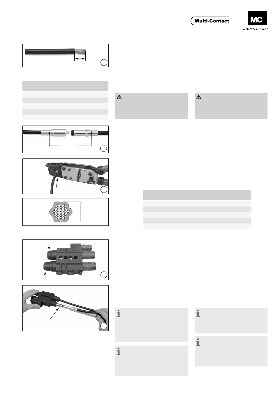
Montage des contacts
principaux
Préparation des câbles
(ill. 1)
Dénuder le câble sur une longueur X
(dépendante de la section). Equiper la
pince à sertir de la matrice adéquate
(Tab.1).
Main contact assembly
Preparation of cables
(ill. 1)
Depending on the conductor cross-
section, strip insulation to dimension
L. Equip crimping tool with appropri-
ate die (Tab.1).
Attention
Diamètre de câble minimal ad-
missible Ø 13 mm
Diamètre de câble maximal ad-
missible Ø 20,5 mm
Attention
Minimal admissible cable diame-
ter Ø 13 mm!
Maximal admissible cable diame-
ter Ø 20,5 mm
Sertissage des contacts prin-
cipaux
(ill. 2)
Positionner le conducteur dans le fыt
а sertir. Il doit apparaître dans l‘orifice
de contrôle.
Crimping the contacts
(ill. 2)
Insert the wire into the contact crimp-
ing sleeve until it appears in the sight
hole.
(ill. 3)
Sertir. Maintenir le conducteur dans
sa position axiale. Après sertissage, le
conducteur ne peut plus être retiré du
fыt а sertir. (Contrôle!)
(ill. 3)
Crimping process according to
MA226. After Crimping, the cable may
not be removed from the crimp barrel.
(Control!).
Mise en place des contacts
(ill. 4)
Adapter la longueur de la sortie de
câble du boîtier isolant (L) au diamètre
du câble. Les diamètres de câble sont
indiqués sur les sorties de câble.
Installing the contacts
(ill. 4)
Shorten the cable grommet on the
insulated housing to suit the cable
diameter. Cable diameters are stated
on the cable grommet.
(ill. 5)
Engager les contacts dans leur loge-
ment respectif situé dans les supports
isolants. En outre, les douilles seront
équipées d’un cône de montage (K).
Introduire complètement le contact
dans son logement avec l’outil de
montage, ce dernier prenant appui sur
la collerette arrière du contact.
Information:
Avant le montage des contacts
dans le boîtier isolant, nous vous
recommandons vivement de les
plonger dans de l’Ethanol ou tout au-
tre alcool industriel.
Mise en garde:
Ne pas utiliser de graisse!
Information:
Selon la rigidité des câbles,
l’utilisation de l’outil de montage
n’est pas obligatoire. Le cône de
montage pour douilles n’en reste pas
moins indispensable.
(ill. 5)
Pre-mount the ends of the contacts
into the contact chambers of the in-
sulated housing. In the case of socket
contacts, also place an insertion cone
(K) onto the contact. Set contact inser-
tion tool against the back shoulder of
the contact and press the contact in
upto the stop.
Note:
Before pressing the contacts into
the housing, be sure to dip them in
Ethanol or industrial alcohol.
Warning: do not use any grease!
Note:
If the stiffness of the cable permits
it, it may be possible to install the
contacts without an insertion tool.
But the insertion cone is required for
socket contacts in any case.
Tab. 1
Section du câble
Conductor cross-section
L±1
(mm)
Matrice
Crimping die
25mm²
16
TB11
35mm²
21
TB13
50mm²
27
TB14,5
70mm²
27
TB17
95mm²
29
TB20
Matrice
Crimping die
Dimension de contrôle max. X
max. control dimension X
TB11
8.8
TB13
10.2
TB14.5
11.4
TB17
13.4
TB20
16.4
Tab. 2