Multi-Contact MA255 Manuel d'utilisation
Page 5
Advanced Contact Technology
www.multi-contact.com
5 / 12
6
7
8
(ill. 6)
Produit d‘étanchéité: convient pour
l‘application d‘utilisation finale.
(ill. 6)
Pottant: appropriate for the end use
application.
Attention
Pour des résultats optimaux, il est
important de suivre les instruc-
tions fournies par le fabricant du
matériau.
Note
Be certain to follow the instruc-
tions for proper use provided by
the material suppliers for optimal
results�
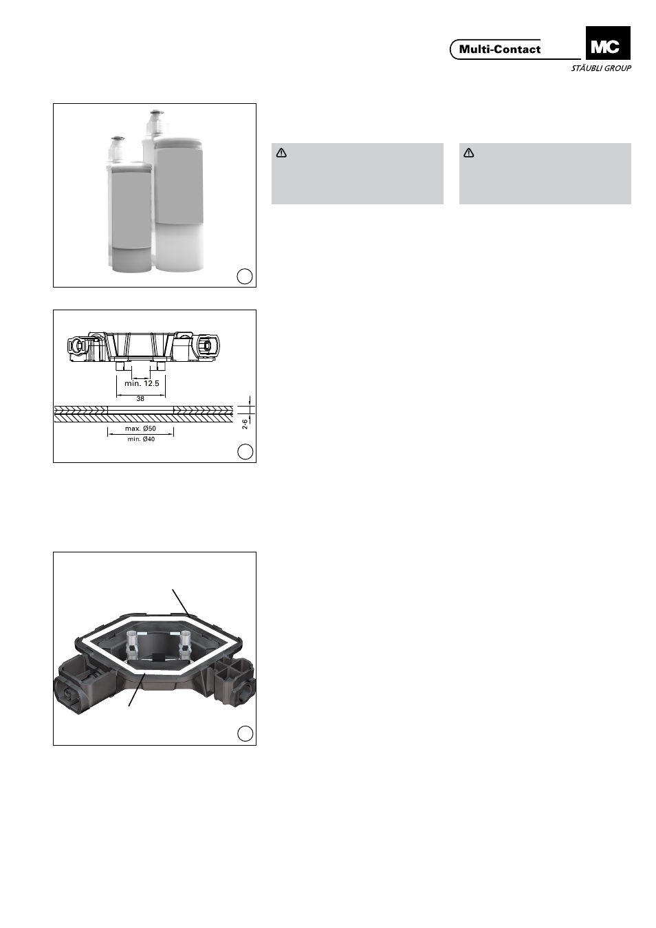
Spécifications pour le module
Module requirements
(ill. 7)
Plan de perçage:
- Trou dans le verre:
Ш 40 - Ш 50 mm
- Rayon d’action du fer à souder:
2-6 mm
(Distance de la surface de montage à
la barre conductrice interne, substrat
inclus
(ill. 7)
Drilling plan:
- Glass hole:
Ш 40 - Ш 50 mm
- Soldertab operating range: 2-6 mm
(Distance from mounting surface to
internal busbar including bonding
agent)
Montage du boîtier de jonc-
tion au dos d’un module PV
Securing the junction box to
the back of a PV module
Pour la préparation et le nettoyage
des surfaces à coller, voir page 9
For preparation and cleaning of
the bonding surfaces see page 9
(ill. 8)
Avec l’applicateur de colle, appliquer
un cordon continu d’environ 4 mm
de large et 1,5 mm de haut au dos du
boîtier de jonction de manière à recou-
vrir complètement la zone de collage.
Appliquer la colle principalement du
côté intérieur de la zone.
La zone de collage est la bande plate
entre les pieds de positionnement de
1mm de haut situés sur la surface de
montage du boîtier de jonction. Une
couverture suffisante de la zone de
collage est nécessaire pour appliquer
correctement le boîtier de jonction. Un
“excès” de colle est permis aussi bien
à l’intérieur qu’à l’extérieur de la zone
de collage du boîtier de jonction.
(ill. 8)
Use the adhesive applicator, dispense
a continuous bead of approximately
4 mm wide and 1.5 mm high to the
back of the junction box to fully cover
the adhesive applicaton path, focusing
on the inside of the path.
The adhesive application path is the
flat track in between the 1 mm tall
standoff cleats located on the mount-
ing surface of the junction box. Suffi-
cient coverage of the adhesion area is
required to properly affix the junction
box. “Squeeze-out” of adhesive both
internal and external to the junction
box adhesion application path is
permitted.
Pieds de positionnement
Stand-off cleats
Zone de collage
Adhesive application path