Multi-Contact MA275 Manuel d'utilisation
Page 6
Advanced Contact Technology
6 / 8
www.multi-contact.com
2 - 6
x
12,2
12,2
+0, 2
- 0,1
+0, 2
- 0,1
15
13
14
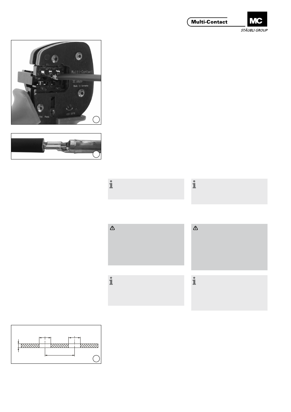
(ill. 13)
Insérer l‘extrémité du câble dénudé
jusqu‘à ce que l‘isolant bute sur la
matrice de sertissage. Fermer complè-
tement la pince à sertir jusqu‘à ce que
le cycle du mécanisme se termine.
Ouvrir la pince et enlever le contact
serti.
(ill. 13)
Insert the stripped cable end until the
insulation comes up against the crimp
insert. Close the crimping pliers com-
pletely, until the ratchet mechanism
cycles completely and the handle
releases. Open the clamp and take out
the crimped contact element.
(ill. 14)
Contrôler visuellement le sertissage.
Vérifier que le sertissage soit bien
fermé, qu‘il contient tous les brins du
conducteur, qu‘il soit symétrique, et
non déformé. Sinon, retirer le sertis-
sage en le coupant et recommencer à
l‘ill. 10.
(ill. 14)
Visually check the crimp. Verify that
the crimp is fully closed, contains all
of the conductor strands, is sym-
metrical and is not poorly formed in
any way. If not, remove the crimp by
cutting it off and start over at ill. 10.
Remarque:
Pour des instructions sur la pince
à sertir PV-CZM..., voir l‘instruction
MA251 sur www.multi-contact.com
Note:
For directions on the operation of
the crimping tool PV-CZM..., please
see operating instructions MA251 at
www.multi-contact.com
Remarques de sécurité pour
le sertissage
Special safety notes regard-
ing crimping
Danger:
Ne pas sertir les câbles avec des
isolants endommagés lors du dé-
nudage! En cas de dommage sur
le câble, la section de l‘isolation
du câble endommagée doit être
coupée et retirée. Recommencer
le dénudage du câble.
Danger:
Do not crimp cables with insula-
tions that were damaged while
stripping!
In case of damage at the cable
isolation the damaged cable
section has to be cut off and
removed. The cable has to be
stripped again.
Remarque:
Veillez à l‘épaisseur de la paroi.
Elle ne doit pas être < à 2 mm et > à
6 mm. Si l‘épaisseur de la paroi est
inférieur à 2 mm, l‘utilisation doit être
validé par le client.
Note:
Please ensure a housing wall
thickness not less than 2 mm and a
maximum of 6 mm. In case of using
a wall thickness below 2 mm the
validation process has to be done by
the customer.
Montage du connecteur
Installation of receptacles
(ill. 15)
Percer la paroi du boîtier. Dimensions
recommandées selon illustration (la
dimension indiquée auparavant est
réalisable, mais doit être vérifiée à la
fin du montage).Les bavures doivent
ensuite être retirées des bords de tous
les trous.
(ill. 15)
Drill the panel wall. Recommended
bore dimension see in the sketch. (the
formally indicated dimension
12,5
+0,2/-0,4
mm ist possible, but shall
be verified in the end use). Subse-
quently, burrs must be removed from
the edges of all bores!
Pour les montages horizontaux ou ver-
ticaux, nous préconisons un entraxe (X)
d‘au moins 25mm.
For both horizontal and vertical
mounting a spacing (X) of at least
25mm is recommended.