Multi-Contact MA220 Manuel d'utilisation
Page 7
Advanced Contact Technology
www.multi-contact.com
7 / 8
13
(ill. 12)
Dévisser la vis sans tête (8) au moyen
de la clй а 6 pans 2 mm (m). Dévisser
la bague de fixation (4) au moyen de la
bague de montage (L) et du tournevis
(n) utilisé comme levier� Monter la
bague de support (k) à la place de la
bague de fixation (4). Celle-ci possède
2 surfaces d‘appui, I et II.
La surface I est prévue pour le démon-
tage du boîtier avant mâle et la sur-
face II pour le démontage du boîtier
avant femelle�
(ill. 12)
Unscrew the setscrew using a hex key
wrench A/F 2 (m)� Unscrew the secur-
ing ring (4) by means of the assembly
ring (L), turning with the screwdriver
(n) as a lever� Fit the supporting ring
(k) in the place of the securing ring
(4)� The support ring has 2 supporting
surfaces, I and II.
Surface I is for dismantling the front
part of the pin housing, and surface
II for dismantling the front part of the
socket housing�
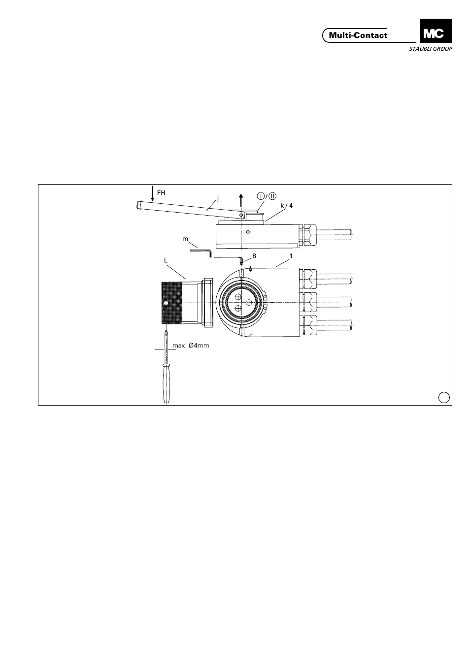
(ill. 13)
Placer ensuite l‘outil de démontage (j)
sur le boîtier avant mâle (I) ou femelle
(II) dans les trous prévus à cet effet.
Serrer les branches de l‘outil de mon-
tage et exercer en même temps une
pression en direction FH pour extraire
le boîtier avant mâle (I) ou femelle (II).
Monter à la main le nouveau boîtier
avant mâle (I) ou femelle (II) dans la
position correcte (rainure correspon-
dant à la goupille de guidage)� Veiller
impérativement à mettre en place le
boîtier avant mâle ou femelle dans le
boîtier arrière qui lui correspond (1,
voir marquage)� Revisser la bague de
fixation (4) au moyen de la bague de
montage (L), puis revisser la vis sans
tête (8) au moyen de la clй а 6 pans 2
mm (m) pour verrouiller la bague de
fixation (4).
(ill. 13)
Then insert the extraction tool (j) into
the holes provided in the front part of
the pin (I) or socket (II) housing. Press
together the arms of the assembly
tool and at the same time press in
direction FH so as to lever out the pin
(I) or socket (II) housing front part.
Fit by hand the new pin (I) or socket
(II) housing front part in the correct
position (slot in line with guide pin)�
Check carefully that the pin or socket
housing front part is fitted into the
correct housing bottom part (1, see
marking)� Screw the securing ring (4)
back in place with the assembly ring
(L), then screw in the setscrew (8) to
fix the securing ring (4) using a hex
key wrench A/F 2 (m)�