Multi-Contact MA220 Manuel d'utilisation
Page 4
Advanced Contact Technology
4 / 8 www.multi-contact.com
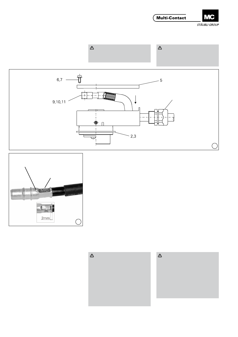
9
10
Sertissage
Crimping
Attention
Enfiler le boîtier arrière (1) et si
nécessaire le presse-étoupe sur le
câble avant de sertir�
Attention
Before crimping, pass the cable
through the lower part of the
housing (1) and the cable gland if
appropriate�
(ill. 9)
Equiper la pince à sertir de la matrice
de sertissage TB11 (25 mm²) ou TB13
(35 mm²).
Introduire le conducteur dans le fыt
а sertir du contact (9, 10, 11) jusqu‘à
ce qu‘il apparaisse dans l‘orifice de
contrôle� Sertir le conducteur en res-
pectant la zone de sertissage
(ill� 10)! Le conducteur doit être visible
dans l‘orifice de contrôle avant et
après le sertissage. Vérifier la qualité
de sertissage en exerçant une traction
sur le conducteur�
(ill. 9)
Fit crimping insert TB11 (25 mm²)
or TB13 (35 mm²) into the crimping
pliers. Insert the individual conductors
into the crimping sleeve of the contact
piece (9, 10, 11) until they appear in
the control hole (ill� 10) of the crimp-
ing sleeve� Crimp conductor in crimp-
ing sleeve� Observe crimping zone!
After / before crimping, the conductor
must be visible in the control hole�
It must not be possible to pull the con-
ductor out of the crimping sleeve�
Montage des pièces de
contact
Fitting the contact pieces
Retirer les conducteurs à travers les
presse-étoupes, puis réenficher les
contacts (9, 10, 11) sur les broches de
contact du boîtier avant mâle (2) ou
femelle (3)�
Pull back the conductors through the
openings of the cable glands� Place
the contact (9, 10, 11) in the correct
position on the contact pins of pin (2)
or socket (3) housing front part�
Attention
Ne serrer le presse-étoupe
qu‘après avoir correctement
enfiché les contacts et aligné
les conducteurs dans le boîtier
arrière (1)!
Couple de serrage presse-étoupe:
3,5 Nm
Couple de serrage écrou de rac-
cord: 2,5 Nm
Revisser le couvercle (5) avec les
vis (6, 7) au moyen de la clй а 6
pans 2,5 mm.
Attention
Do not tighten the cable gland
until the contact pieces have
been correctly fitted on the pins
and the conductors aligned in the
housing bottom part (1)
Cable gland torque: 3.5 Nm
Grip nut torque: 2.5 Nm
Screw the cover (5) back in place
with screws (6, 7) using hex key
wrench A/F 2�5�
Presse-étoupe
Cable gland
Zone de sertissage
Crimping zone
Orifice de contrôle
Control hole