Multi-Contact MA087 Manuel d'utilisation
Page 3
Advanced Contact Technology
www.multi-contact.com
3 / 8
1
2
L
3
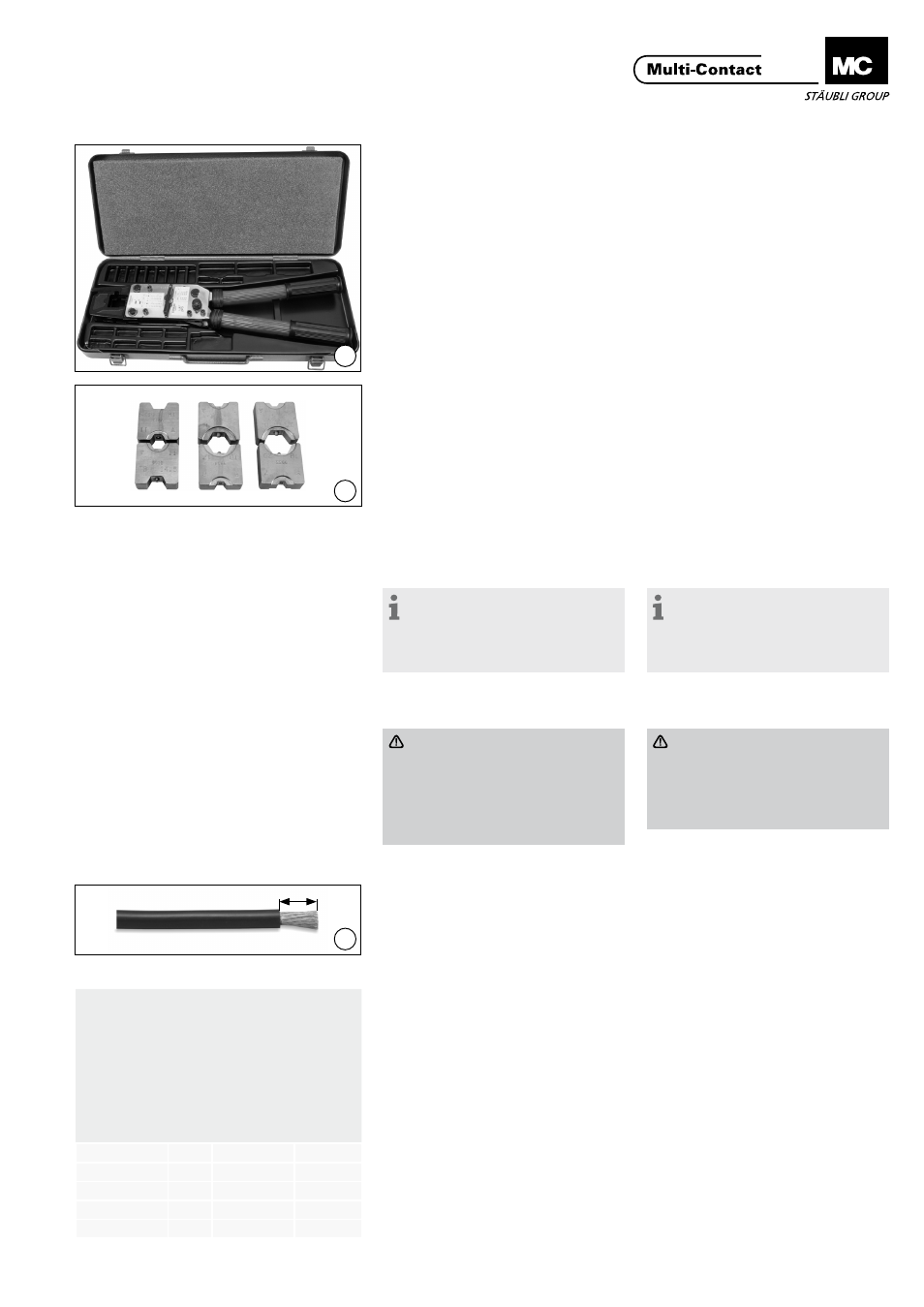
Outillage nécessaire
Tools required
(ill. 1)
Pince à sertir M-PZ-T2600
No� de Cde� 18�3710
(ill. 1)
Crimping pliers M-PZ-T2600
Order No� 18�3710
(ill. 2)
Matrice pour section du conducteur
10 mm
2
,
TB8-17, No� de Cde� 18�3711
Matrice pour section du conducteur
16 mm
2
+ 35 mm
2
,
TB9-13, No� de Cde� 18�3712
Matrice pour section du conducteur
25 mm
2
+ 50 mm
2
,
TB11-14,5, No� de Cde� 18�3713
(ill. 2)
Insert for conductor cross section
10 mm
2
,
TB8-17, Order No� 18�3711
Insert for conductor cross section
16 mm
2
+ 35 mm
2
,
TB9-13, Order No� 18�3712
Insert for conductor cross section
25 mm
2
+ 50 mm
2
,
TB11-14,5, Order No� 18�3713
Remarque:
Pour les instructions sur le fon-
ctionnement de la pince à sertir,
veuillez consulter le mode d’emploi
MA226, www.multi-contact.com
Note:
For directions on the operation of
the crimping tool, please see opera-
ting instructions MA226 at
www.multi.contact.com
Préparation du câble
Cable preparation
Attention
Pour que le connecteur réponde
aux exigences de l’indice de
protection IP54 lors du branche-
ment, glisser une gaine ther-
morectractable avec de la colle
interne sur chaque câble�
Attention
If the connector is to meet the
requirements of protection class
IP54 when mated, slide a shrink-
on sleeve with internal adhesive
onto each cable�
Dénudage du câble
Cable stripping
(ill. 3)
Dénuder l‘isolation du câble sur la lon-
gueur L, selon la section du conduc-
teur (Tab� 1)�
(ill. 3)
Strip the insulation from the cable
over the length L, according to the
conductor cross-section (Tab 1)�
Tab. 1
Section du conducteur Conductor cr
oss-section
L±1
(mm)
Matrice de sertissage Crimping d
ie
Dimension max. X Max. d
imension X
10 mm²
13�5
TB8
6�4
16 mm²
13�5
TB9
7�6
25 mm²
16
TB11
8�8
35 mm²
21
TB13
10�3
50 mm²
27
TB14�5
12�1