Multi-Contact MA265 Manuel d'utilisation
Page 7
Advanced Contact Technology
Advanced Contact Technology
12 / 16 www.multi-contact.com
www.multi-contact.com
13 / 16
19
20
(ill. 19)
Quand l’opération d’application est terminée, le piston
presseur peut être ramené dans sa position initiale� L’outil
auxiliaire complet doit maintenant être soulevé verticalement
ou le module PV abaissé verticalement d’au moins 20mm
pour libérer le boîtier de jonction de son support� Ensuite
seulement, l’outil auxiliaire complet ou le module PV peut
être basculé sur le côté et enlevé.
(ill.19)
When the pressing-on process is completed, the pressure
pad can be returned to ist starting position� The complete
auxiliary tool must now be lifted vertically, or the PV module
lowered vertically� The raising or lowering distance must be at
least 20mm in order fully to release the junction box from ist
mounting� Only now may the complete auxiliary tool or the PV
module be pivoted away to the side�
Remarque importante concernant l‘assemblage
collé
Important note on the adhesive bond
Après la pose correcte du boîtier de jonction, la colle met
environ 72 heures à durcir complètement� Ce n’est qu’après
ce délai que l’assemblage collé possède l’étanchéité requise
pour pouvoir être exposé à l’humidité ambiante ou à des
travaux de nettoyage. Une manipulation normale (transport,
etc�) est possible déjà peu de temps après le collage�
After the junction box has been correctly fixed in place, the
adhesive bond needs approximately 72 hours to cure com-
pletely� Only after this time does the bond have the necessary
impermeability so that it can be exposed to environmental
moisture or subjected to cleaning operations� Normal handling
(transport) is already possible a short time after bonding�
Même 72 heures après l’opération, s’assurer que le boîtier
de raccordement n’est pas soumis à une pression/poussée
excessive et/ou prolongée, résultant d’un empilage horizontal
ou vertical du module ou d’une tension/pression des câbles
de connexion� Veuillez noter toutes les instructions de sécu-
rité sur la page 2 de ces instructions de montage�
Even after 72 hours, make sure that the junction box is not
subjected to excessive and/or sustained pressure/pushing
as a result of horizontal or vertical stacking of the module or
tension/pressure from connecting cables� Please note all the
safety instructions on page 2 of these assembly instructions�
Remarques concernant le montage du boîtier
de jonction sur le module PV sans l‘outil
PV-JB-WZ LC SP
Notes on the fixing of the junction box on the PV
module without the use of the MC auxiliary tool
PV-JB-WZ LC SP
Pour garantir un montage dans les règles de l’art, l’utilisation
de l’outil
PV-JB-WZ LC SP est vivement recommandée� Cet
outil a été spécialement conçu pour garantir la position cor-
recte du boîtier par rapport à la sortie des conducteurs plats�
Seul le respect des procédures décrites en pages 5 à 10 est
de nature à garantir un montage correct�
For the correct mounting of the junction boxes we recommend
that the MC tool
PV-JB-WZ LC SP should always be used�
This tool has been specially developed to ensure that the junc-
tion box is correctly positioned in relation to the contact ribbon
outlet� Correct mounting cannot be guaranteed unless the
instructions on pages 5 to 10 and the setup dimensions stated
there are carefully observed�
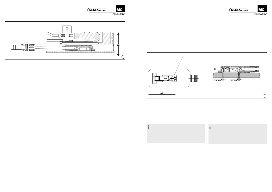
(ill. 20)
L’illustration 20 présente la position du boîtier et des conduc-
teurs plats à l’état monté, lorsque le montage a été réalisé
selon les procédures décrites en pages 5 à 10�
(ill. 20)
Ill� 20 shows the geometry of the junction box and the contact
ribbon outlet after the junction box has been fixed in place, if
this has been done in accordance with pages 5 to 10 of these
instructions�
Dans le cas où vous souhaiteriez vous dispenser de l’utilisa-
tion de l’outil MC pour mettre en oeuvre un autre procédé de
montage, l’ill� 20 vous servira de référence�
If you nevertheless decide to work without the special MC tool
and to use your own method or an auxiliary tool of your own,
you can use ill� 20 as a guide�
Remarque:
Adapter la longueur du conducteur plat au process de
montage.
Après montage du boîtier, s‘assurer que le conducteur plat
n‘est pas en contact avec la feuille adhésive et est distant d‘au
moins 1 mm.
Veiller à ce que les conducteurs situés à l’intérieur du boîtier ne
causent pas de courts-circuits.
Note:
The length of the contact ribbon must be adapted to the
installation procedure.
After the junction box has been fixed in place, there must be
no contact between the contact ribbon and the adhesive foil.
The spacing must be at least 1 mm.
Make sure that the ribbons inside the box cannot cause short
circuits.
Trou de sortie de la bande de contact
Exit hole for contact ribbon
Distance minimale entre le conducteur plat et la feuille adhésive à
l‘état monté: 1mm!
Minimum distance between contact ribbon and adhesive foil after
mounting: 1mm!