Multi-Contact MA265 Manuel d'utilisation
Page 5
Advanced Contact Technology
Advanced Contact Technology
8 / 16 www.multi-contact.com
www.multi-contact.com
9 / 16
9
N
10
13
B
14
12
11
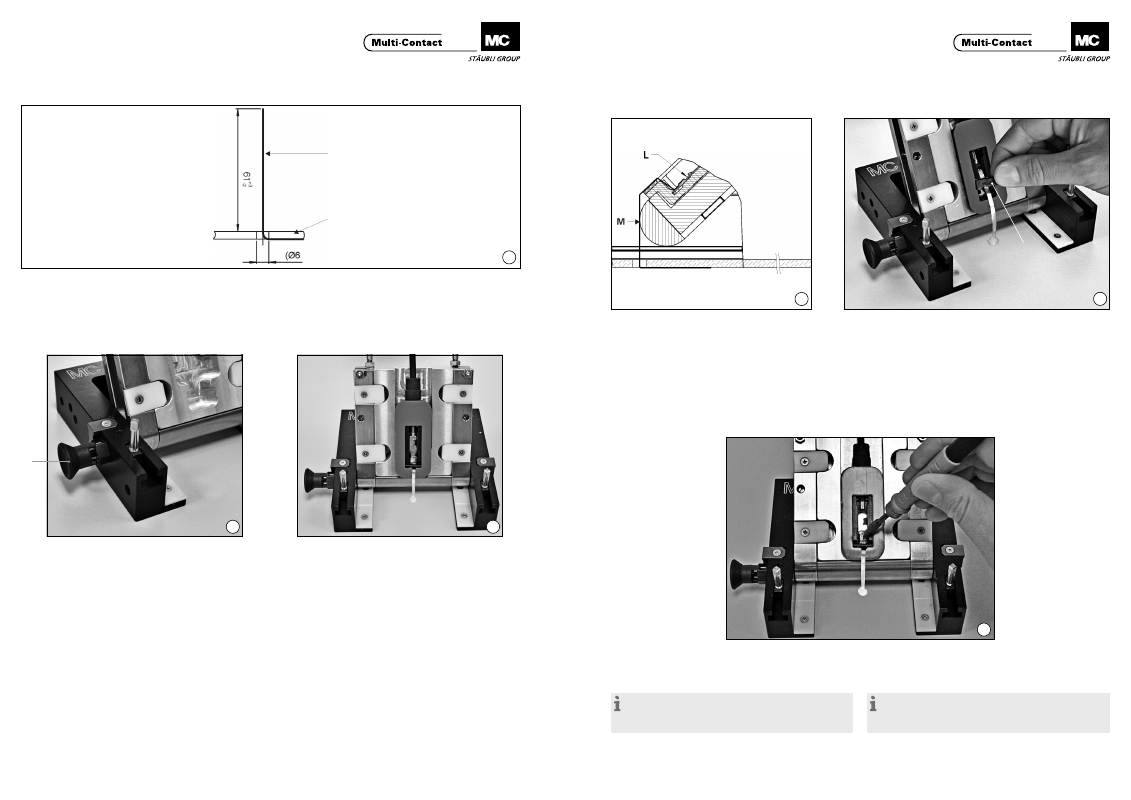
Préparation des conducteurs plats
Preparation of the flat ribbon conductors
(ill. 9)
Les conducteurs plats doivent avoir une longueur de 61 mm
ou être coupés à cette longueur� Il est possible de monter
des conducteurs plats jusqu’à une largeur de 6,5 mm.
(ill. 9)
Flat ribbon conductors should have a length of 61 mm or be
cut to this length� Ribbon conductors with a width of up to
6,5 mm can be fitted.
Insertion du boîtier de jonction dans l’outil au-
xiliaire PV-WZ-JB/LC
Inserting the junction box in the auxiliary tool
PV-WZ-JB/LC
(ill. 10)
Avant l’insertion du boîtier de jonction dans l’outil de mon-
tage, l’axe d’arrêt “N” doit se trouver dans la position initiale
précontrainte�
(ill. 10)
Before the junction box is inserted in the assembly tool, the
locking pin “N” should be in the spring-loaded starting posi-
tion�
(ill. 11)
Pour insérer le boîtier de jonction dans l’outil de montage,
pousser légèrement en arrière le support de boîtier de
jonction de façon à faire reculer la broche d’arrêt (ressort
de pression tendu)� Dans cette position, insérer le boîtier de
jonction et enfoncer le câble de connexion dans la pince à
ressort de l’étrier de retenue de câble. Aprés avoir inséré le
boîtier de jonction, déplacer de nouveau le support de boîtier
de jonction légèrement vers l’avant (position initiale) de façon
que la broche d’arrêt puisse rentrer dans l’ouverture prévue
à cet effet dans le boîtier de jonction (ressort de pression
détendu)�
(ill. 11)
To insert the junction box in the assembly tool, the junction
box receptacle is pushed back slightly so that the locking pin is
moved backwards (pressure spring under tenstion)� In this po-
sition the junction box is inserted and the connecting cable is
pressed into the spring clips of the calbe holder. After inserting
the junction box, the junction box receptacle is again moved
slightly forwards (starting position) so that the locking pin can
enter the opening provided for it in the junction box (pressure
spring de-tensioned)�
Conducteur plat
Flat ribbon conductor
Module PV
PV module
Montage des conducteurs plats
Fitting the flat ribbon conductors
(ill. 12)
Appliquer le conducteur plat “M” légèrement tendu sur la
face avant du boîtier (éventuellement avec un outil auxiliaire :
pincette et tournevis) jusqu’à la pièce de contact “L” pourvue
d’étain de soudage�
(ill. 12)
Draw the ribbon conductor “M” over the front of the housing
under slight tension (if necessary with the aid of tweezers and
screwdriver) as far as the tinned contact part “L”�
(ill. 13)
Fixer ensuite le conducteur plat avec la bride PV “B” fournie
à part (enfoncer jusqu’en butée la bride PV dans l’emplace-
ment prévu à cet effet dans le boîtier de jonction)�
(ill. 13)
The ribbon conductor should then be fixed with the PV retainer
“B” which is supplied loose (press PV retainer as far as it will
go into the recess provided in the junction box)�
(ill. 14)
Souder le conducteur plat avec la pièce de contact PV� Tem-
pérature de soudage 320 °C – 450 °C (en cas d’utilisation du
flux recommandé).
(ill. 14)
Solder ribbon conductor to the PV contact part� Solder tem-
perature 320 °C – 450 °C (with use of the recommende flux).
Remarque:
Il n’est pas nécessaire d’apporter de la soudure supplé-
mentaire. MC recommande l’addtion de flux décapant 950E
(société Kester, www.kester.com).
Note:
It is not necessary to apply on additional solder.
MC recommends the addition of soldering flux 950E (supplier
Kester, www.kester.com).