Multi-Contact MA075 Manuel d'utilisation
Page 5
Advanced Contact Technology
www.multi-contact.com
5 / 8
10
W
A
12
11
Druckpunkt
Actuator
P
oint de pr
ession
(ill.10)
Introduire la broche dans le départ
coudé. Aligner la broche de telle façon
que le marquage W soit bien visible
au cours de l’embrochage.
Serrer les vis cruciformes M6 et
l‘écrou M6.Couple 4 Nm.
Raccordement: voir ill�7, 8 page 4/8
(ill.10)
Insert plug into angle adapter�
Align plug so that marking W is visible
during plugging�
Tighten Philips screws M6 and nuts
M6. Torque 4 Nm.
Connection see ill� 7, 8 page 4/8
Montage du couvercle de pro-
tection
Protective cover assembly
voir instructions de montage MA036
sous www�multi-contact�com
see assembly instructions MA036
under www�multi-contact�com
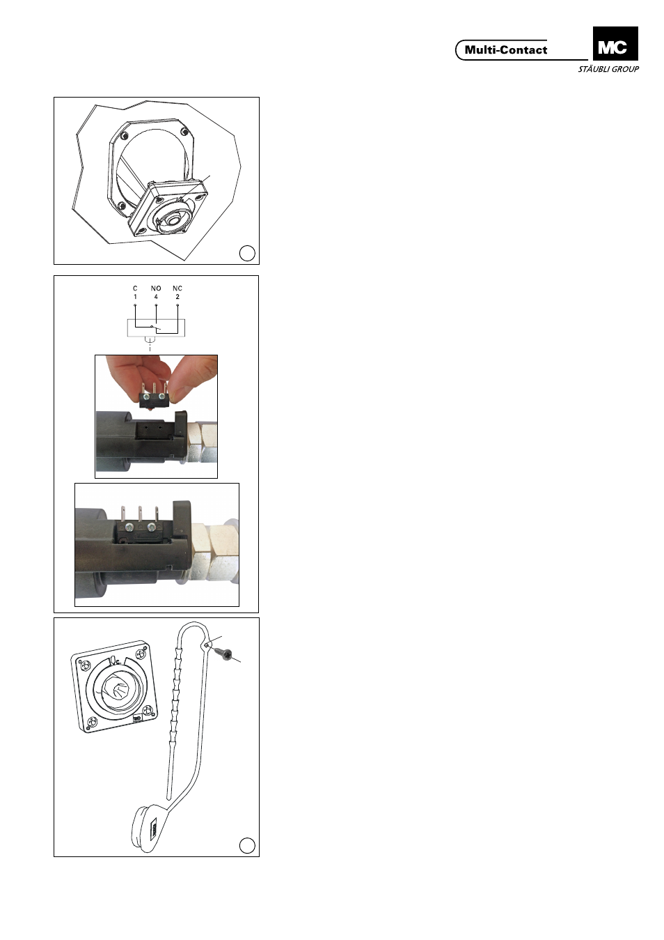
Montage du micro-rupteur
Installation of microswitch
(ill. 11)
Fixer le micro-rupteur sur la broche
avec des vis PT. Il s’agit d’un micro-
rupteur inverseur 6 A, 250 VAC, à trois
contacts 2.8 x 0.5.
Remarque:
Respectez l’orientation du micro-
rupteur lors du montage.
(ill. 11)
Fasten microswitch to plug with PT-
screw. The microswitch contact is a
changeover contact. Type of con-
nection: 3 plug connectors 2.8 x 0.5,
switching capacity 6 A, 250 VAC.
Note:
Observe the orientation when
assembling the microswitch!
Contrôle du micro-rupteur
Functional check of micro-
switch
Le micro-rupteur doit s’enclencher
avant même que le verrouillage ne
soit réalisé. Il indiquera ainsi que le
contact est établi�
Remarque:
Le verrouillage n’est définitivement
réalisé qu’après embrochage com-
plet des deux connecteurs.
By switching immediately prior to
engagement of the interlock, the
microswitch indicates that the plug
connection is engaged�
Note:
Correct interlocking is achieved
only after engagement.
Montage du bouchon de pro-
tection
Fitting the protective cap
(ill. 12)
Le bouchon de protection est emman-
ché jusqu’en butée par l’avant sur la
broche. La cordelette de fixation peut
être vissée au niveau de l’oeillet (A).
(ill. 12)
The protective cap is pushed into the
plug from the front as far as it will go�
The cord lanyard can be screwed to
the eyelet (A).