Multi-Contact MA075 Manuel d'utilisation
Page 4
Advanced Contact Technology
4 / 8
www.multi-contact.com
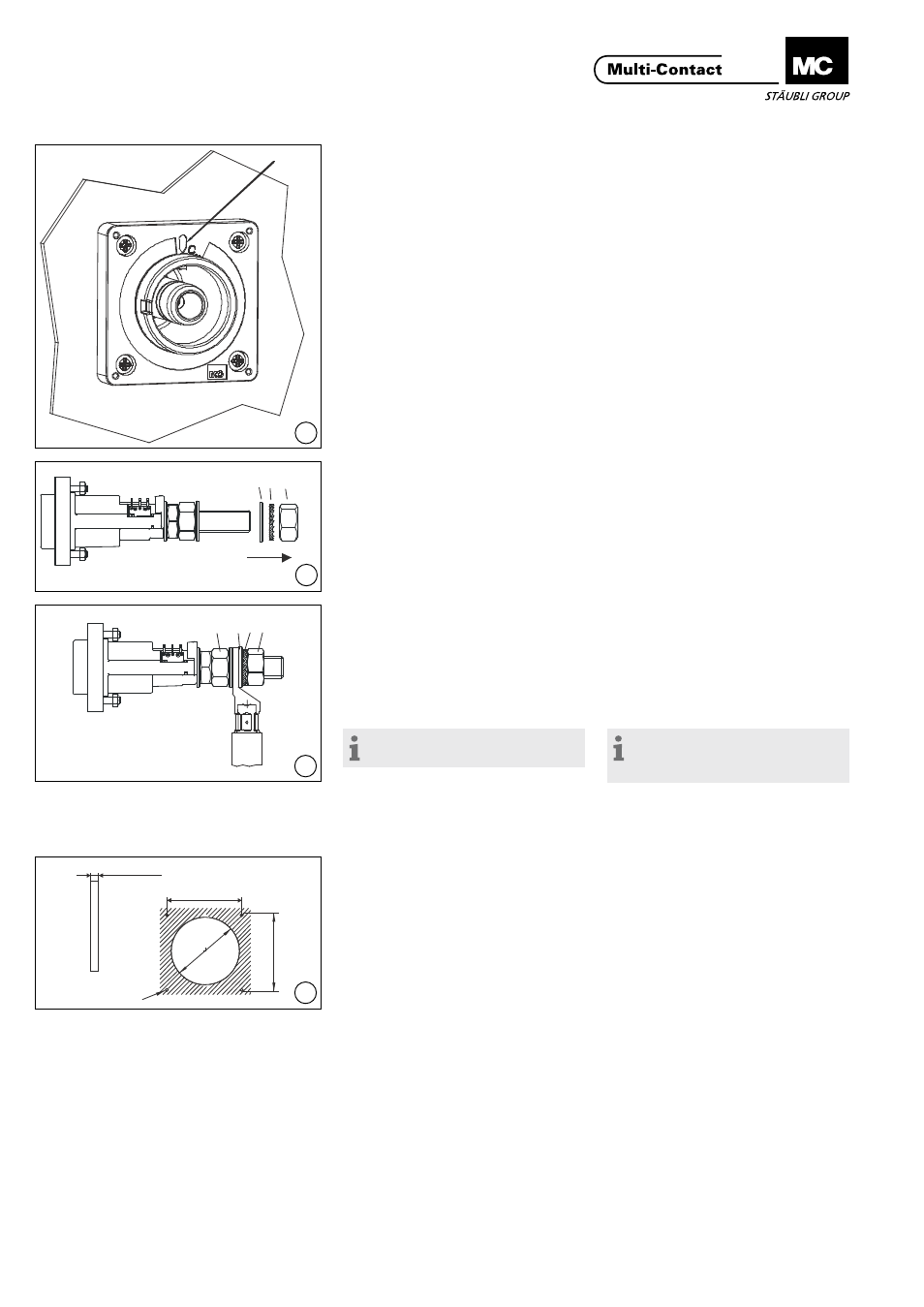
6
W
4 5 6
7
7 4 5 6
8
4 x Ш6,5
Ш1
10
93±0,2
93
±
0,
2
min. 3mm
9
(ill. 6)
Introduire la broche dans le panneau�
Aligner la broche de telle façon que le
marquage W soit bien visible au cours
de l’embrochage.
Serrer les vis cruciformes M6 et
l‘écrou M6. Couple 4 Nm.
(ill.6)
Insert plug into front panel�
Align plug so that marking W is visible
during plugging�
Tighten Philips screws M6 and nut
M6. Torque 4 Nm.
Raccordement
Connection
(ill. 7)
Démonter l‘écrou 6, la rondelle éven-
tail 5 et la rondelle 4 du filetage.
(ill. 7)
Remove nut 6, lock washer 5 and
washer 4 fromscrew thread�
(ill. 8)
Engager la cosse avec le câble serti
sur l’embout fileté. Remonter l’écrou
9, la rondelle et la rondelle éventail�
Serrer la cosse avec l’écrou et la clé
dynamométrique 30 mm et le contre-
écrou avec la clй а fourche 30 mm.
Couple de serrage 52 Nm
Remarque:
Ne pas contrer sur l’isolation!
(ill. 8)
Slip cable lug with pre-assembled
cable onto the thread� Reinstall nut,
washer and lock washer�
Tighten nut with the torque spanner
30 mm A/F and secure it with nut and
the open-end spanner 30 mm A/F.
Tightening torque 52 Nm
Note:
Do not lock-tighten on the insula-
tion!
Montage du connecteur
départ coudé
Connector assembly in angle
adapter
(ill. 9)
Percer le panneau selon le plan de
perçage�
Monter la sortie coudée sur le
panneau frontal par l‘avant, avec le
raccordement de l‘ID/S dirigé vers le
bas� Serrer les vis cruciformes M6 et
l‘écrou M6. Couple 4 Nm.
(ill. 9)
Drill front panel according to drilling
plan�
Mount angle adapter on the panel
from the front so that the ID/S con-
nection points downwards�
Tighten Philips screws M6 and nuts
M6. Torque 4 Nm.