2 before you begin, 1 about your combination oven, 2 combination installations – Bosch 500 Series 30 Inch Double Speed Combination Electric Wall Oven Installation Instructions Manuel d'utilisation
Page 5: 3 parts included, 1 additional parts included for combination ovens, 4 tools and parts needed, 5 power requirements and grounding, 3 package removal
Before you begin
en-us
5
Before you begin
2 Before you begin
Before you begin
Read these instructions before you begin to install your
appliance.
2.1 About your combination oven
Here you can find general information about the installa-
tion of your combination oven.
¡
Some Bosch ovens are sold as combinations. Each
combination includes two built-in ovens: a conventional
wall oven, which must be installed as the lower oven,
and an upper oven that is either a speed oven, a steam
convection oven or a microwave.
¡
For ease of installation and improved alignment, the
oven components are assembled together in the cus-
tomer’s home rather than at the factory.
¡
Each of the components are packed in separate boxes,
which are strapped together prior to shipping.
¡
The combination ovens are approved for use in a single
cutout, using single power connection.
¡
The conventional oven is designed with an oven-
mounted junction box on top, which is used for connect-
ing the upper oven power cable.
¡
The hardware required for mounting the speed oven,
the steam convection oven or the microwave on top of
the conventional oven is delivered inside the conven-
tional oven box.
¡
Each of the combination oven components has its own
rating plate with model number (E-Nr.), production num-
ber (FD) and consecutive numbering (Z-Nr.), etc.
2.2 Combination installations
For combination installations with other Bosch products
(i.e. cooktop over oven, etc.), refer to the Approved Com-
bination Guide located in the manual kit or on our website
for additional clearance requirements for your specific in-
stallation.
2.3 Parts included
After unpacking all the parts, check for any damage in
transit and for completeness of delivery.
8 x Oven mounting screws
(located in the red poly bag
in the broil pan package)
Refer to enclosed leaflet
SCREW INSTALLATION
Additional parts included for combination ovens
2 x Universal connector
brackets
(in parts box on top of
oven)
10 x Stud screws
6 x Shoulder screws
(located in red bag inside
the parts box)
1 x Decorative trim piece
(located in the plastic bag
affixed to the oven top)
2.4 Tools and parts needed
Prepare these tools and accessories before you start to in-
stall your appliance.
¡
Pencil
¡
Measuring tape
¡
Level
¡
T-20 star bit screwdriver
¡
Cross head screwdriver
¡
Drill with bit 1/8"
¡
Knife
¡
Safety gloves
2.5 Power requirements and grounding
The outlet must be properly grounded in accordance with
all applicable codes.
Package removal
3 Package removal
Package removal
Protect any finished flooring before you move the oven.
3.1 Removing the packaging from built-in
single and double ovens
1.
Cut the box straps.
2.
Open the top of the carton and remove the top wood
frame.
3.
Remove the carton by lifting it up and off the unit.
Alternatively you can carefully cut along the cut line on
the back left side of the carton with a blade shorter than
3/4" (20 mm).
4.
Place the unit in front of the cabinet where it is to be in-
stalled. The unit should be in line with the cabinet
cutout.
Leave the unit on the packaging base until it is ready to
be lifted into the cabinet cutout.
5.
Remove all internal protective packaging, racks, acces-
sories, and instruction manuals from the oven cavity.
6.
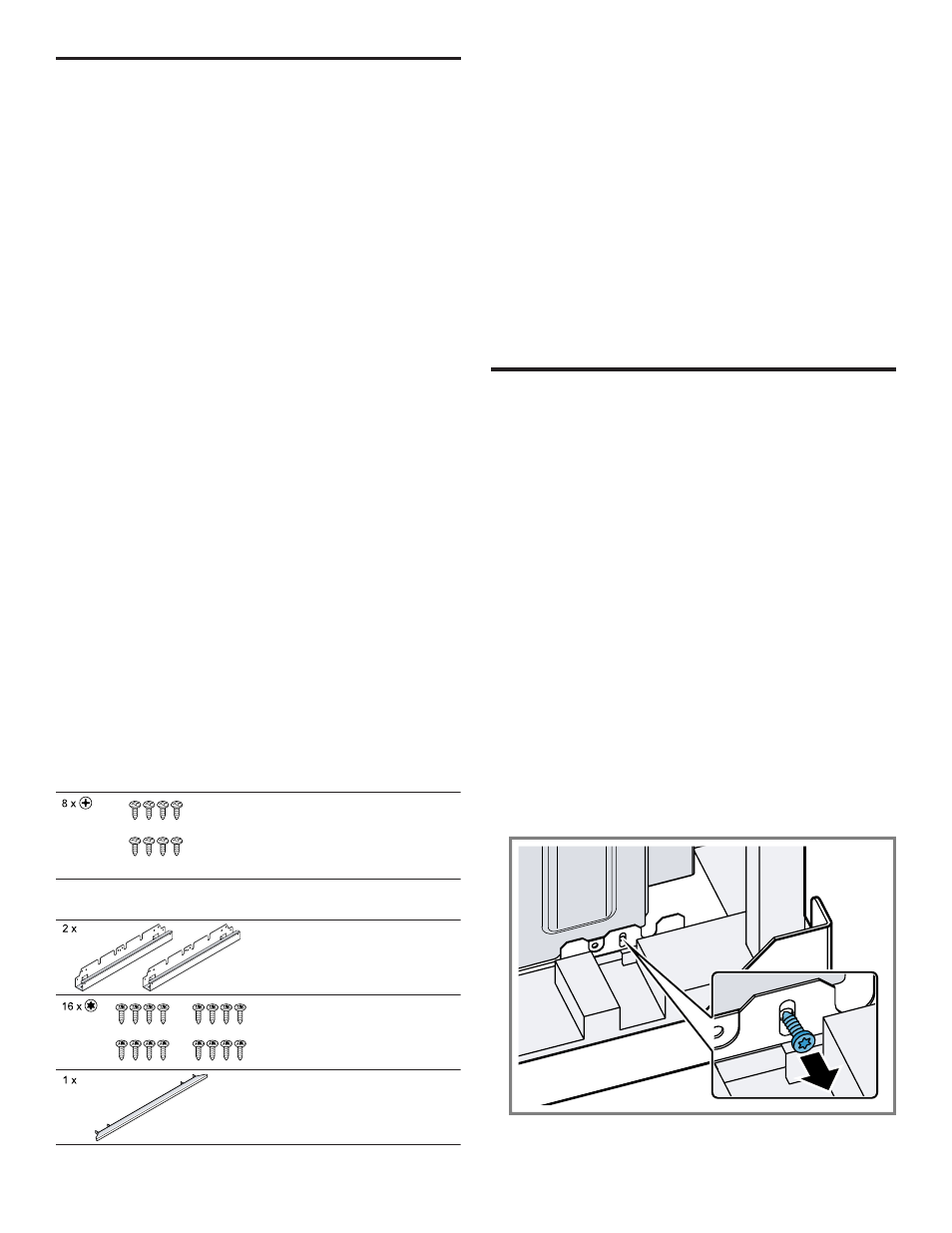
Remove the packaging brackets.
‒
With a T-20 star bit screwdriver, remove the screws
that go through the slotted holes in the mounting
brackets on the left and right side.
‒
Do not remove any additional screws from the oven.
a
The oven is released from the packaging base.
a
The brackets remain in the packaging base.