Ethernet / profinet interbus profibus – Multi-Contact MA213-04 Manuel d'utilisation
Page 4
Advanced Contact Technology
4 / 8
www.multi-contact.com
B
S
Ethernet / Profinet
Interbus
Profibus
7
6
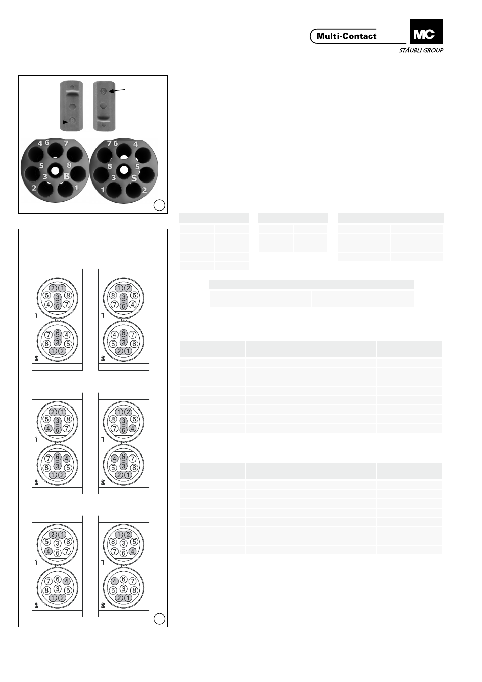
Montage des contacts dans
l‘insert
Contact assembly in inserts
(ill. 6)
Les inserts sont marqués d’un B pour
le côté douille et d’un S pour le côté
broche� Les numéros de contact
se trouvent sur la face arrière� Les
contacts doivent être introduits côté
face numérotée�
(ill. 6)
The female insert is marked with a B,
the pin insert is marked with an S� The
contact numbers are on the back side�
The contacts will be inserted from
back side�
Disposition des contacts des
supports de contacts
Contact arrangement of the
contact carrier
(ill. 7)
(Vue de la face de raccordement)
(ill. 7)
(Seen from the termination side)
Configuration avec 4 paires T568A
Configuration with 4 pairs T568A
Configuration avec 4 paires T568B
Configuration with 4 pairs T568B
Côté broche
Côté douille
Pin side
Socket side
Interbus
DO
1
/DO
2
DI
3
/DI
6
COM
4
Profibus
Line A
1
Line B
2
GND
4
Ethernet & Profinet
TX+
1
TX-
2
RX+
3
RX-
6
CANbus
Configuration individuelle selon
spécifications BUS
Individual configuration accor-
ding to BUS specifications
Contact No.
Paire No.
Pair No.
Couleur
Colour
1
1
blanc/vert
white/green
2
1
vert
green
3
2
blanc/orange
white/orange
4
3
bleu
blue
5
3
blanc/bleu
white/blue
6
2
orange
orange
7
4
blanc/brun
white/brown
8
4
brun
brown
Tab. 2
Tab. 3
Contact No.
Paire No.
Pair No.
Couleur
Colour
1
1
blanc/orange
white/orange
2
1
orange
orange
3
2
blanc/vert
white/green
4
3
bleu
blue
5
3
blanc/bleu
white/blue
6
2
vert
green
7
4
blanc/brun
white/brown
8
4
brun
brown