Outillage nécessaire tools required, Dénudage du câble stripping the cable, Montage du contact contact assembly – Multi-Contact MA092 Manuel d'utilisation
Page 3
Advanced Contact Technology
www.multi-contact.com
3 / 8
1
Tab. 1
2
3
Outillage nécessaire
Tools required
Les outils suivants (disponibles sur
demande) sont recommandés pour la
confection de contacts avec câbles à
gradient d’indice�
The following tools are recommended
for assembling the contacts with
GI-cables (available on request).
■
Pince à sertir hexagonale,
910CZ00100002
■
Pince à dénuder 0,18 mm,
910AB00118001
■
Pince à dénuder 0,3 mm,
910AB00130001
■
Outil à entailler, 910FRW0100001
■
Colle bi-composant,
9102KKFERTIG1
■
Seringue à usage unique et canule,
910SPRITZ0001
■
Papier de polissage 5 µm,
910PB00105001
■
Papier de polissage 0,3 µm,
910PB00100301
■
Four de cuisson, 910AO00100001
■
Disque de polissage, 910PS0ST00001
■
Microscope 100x (sans adaptateur),
910MIKRO10002
■
Adaptateur, 910MIADAST002
■
Cutter
■
Ciseaux à Kevlar
■
Hexagonal crimping pliers,
910CZ00100002
■
Insulation stripper 0.18 mm,
910AB00118001
■
Insulation stripper 0.3 mm,
910AB00130001
■
Fiber cleaving tool,
910FRW0100001
■
Two-component adhesive,
9102KKFERTIG1
■
One-way syringe with needle,
910SPRITZ0001
■
Polishing sheet 5 µm,
910PB00105001
■
Polishing sheet 0.3 µm,
910PB00100301
■
Heat oven, 910AO00100001
■
Polishing disc, 910PS0ST00001
■
100x microscope (without adapter),
910MIKRO10002
■
Adapter, 910MIADAST002
■
Cutter
■
Kevlar cutter
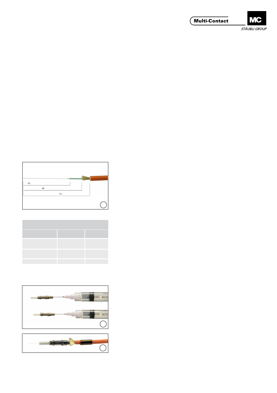
Dénudage du câble
Stripping the cable
(ill. 1)
Couper le câble à la longueur souhai-
tée�
Dénuder la gaine du câble au cut-
ter sur la longueur indiquée dans le
tableau 1�
Raccourcir le fil pour rétention de
câble avec les ciseaux à Kevlar�
Enlever le tube de protection et le
revêtement secondaire avec la pince à
dénuder 0,3 mm.
Enlever le revêtement primaire avec la
pince à dénuder 0,18 mm.
Enlever les éventuels résidus se trou-
vant sur la fibre avec un chiffon doux.
(ill. 1)
Cut the cable to length�
Remove the cable cladding using the
cutter according to the dimensions in
Table 1�
Use the Kevlar cutter to shorten the
strain relief cord�
Remove the buffer tube and the
secondary coating using the 0.3 mm
insulation stripper�
Remove the primary coating using the
0.18 mm insulation stripper.
Remove any residue on the fiber using
a soft cloth (microfiber cloth).
Montage du contact
Contact assembly
(ill. 2)
Préparer une quantité adéquate de
colle�
Remplir le contact de colle avec la
seringue à usage unique�
Glisser le fût de sertissage sur le câble
(ill. 2)
Prepare an appropriate amount of
adhesive�
Fill the contact with adhesive using
the one-way syringe with needle�
Push the crimp sleeve onto the cable�
(ill. 3)
Insérer la fibre dans le contact
jusqu’en butée. L’extrémité de la fibre
devrait déborder la virole d’environ
20 mm.
(ill. 3)
Insert the fiber into the contact until it
stops. The end of the fiber should pro-
ject about 20 mm out of the ferrule.
Longueur de dénudage
Strip lengths
Désignation
Description
Contact femelle
Socket contact
Contact mâle
Pin contact
CJ - gaine de câble
CJ - Cable cladding
40 mm
40 mm
AF - Kevlar Secon-
dary Coating
35 mm
35 mm
FC - Coating
30 mm
30 mm