Multi-Contact MA048 Manuel d'utilisation
Page 5
Advanced Contact Technology
www.multi-contact.com
5 / 8
10
11
12
Montage
Assembly
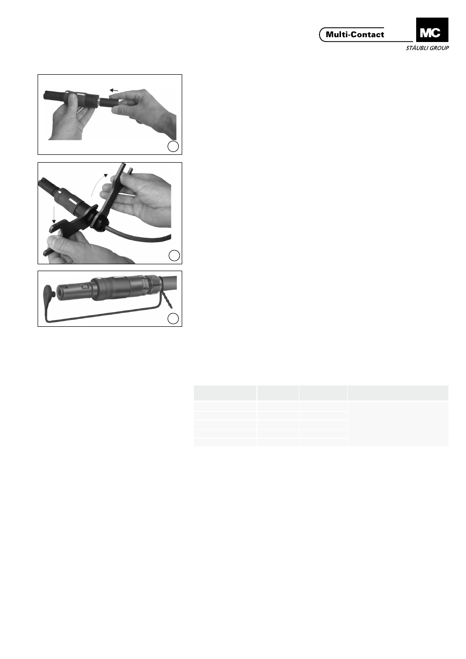
(ill. 10)
Introduire le corps de contact dans
le boîtier isolant et tourner jusqu’à ce
que le corps de contact s’enfonce et
soit bloqué en rotation�
(ill. 10)
Slip the contact insert into the insula-
tion and turn until the contact insert
falls deeper and can not be turned�
(ill. 11)
Serrer le presse-étoupe� Pour serrer et
contrer, MC recommande l’utilisation
de deux outils GS33/42 (voir ill. 3)
identiques pour éviter d’endommager
le filetage.
(ill. 11)
Tighten the cable gland� For tight-
ening and fixing with the locknut,
MC recommen d using two identical
GS33/42 see ill. 3 tools to prevent
over-tightening of the thread�
Montage du bouchon de
protection
Fitting the protective cap
(ill. 12)
Pour solidariser le bouchon de protec-
tion avec le connecteur, former une
boucle avec la cordelette de fixation et
enfiler son extrémité à travers l‘oeillet.
(ill. 12)
To attach the protective cap to the
plug connector with the securing
cord, form a loop and push the end of
the cord through the eyelet�
Codage:
Coding:
Il existe jusqu‘à 5 possibilités de
codage, identifiées de C1 à C5.
En vue de garantir une parfaite inter-
changeabilité, nous vous recomman-
dons le codage suivant:
There are a maximum of 5 coding pos-
sibilities, designated from C1 to C5�
The following coding is recommended
to safeguard the interchangeability:
Désignation
Designation
Symbole
Symbol
No de codage
Coding-No.
Couleur
Colour
Phase 1
L1
C1
A définir par le client
To be defined by the customer
Phase 2
L2
C2
Phase 3
L3
C3
Neutre/Neutral
N
C4
Terre/ground
PE
C5
Remarque importante:
Une broche codée ne pourra pas être connectée à une douille
avec un codage différent (les No� de codage sont apposés à
côté des marquages blancs)�
Phase d‘embrochage:
Ces connecteurs sont équipés d‘un système de verrouillage
à baïonnette� Aligner les marquages blancs rapportés sur la
douille et la fiche. Connecter les deux parties jusqu‘en butée,
puis pousser axialement tout en imprimant à la broche un
mouvement de rotation relatif de 50° vers la droite. Relâcher.
La connexion doit alors être verrouillée�
Phase de débrochage:
Pousser la broche dans l‘axe, tout en lui imprimant un mouve-
ment de rotation de 50° vers la gauche, de sorte à aligner les
marquages blancs (apposés sur les deux parties) sur un même
axe� Retirer la broche de la douille�
Important notice:
Plugs can only be inserted into sockets with the same code no�
(inscribed code is next to the white markings)�
Plugging procedure:
This plug connector is equipped with a bayonet locking sys-
tem� The white markings on the plug and socket have to be
lined up� Mate plug with socket to the stop, then insert further
with axial pressure and turn simultaneously the plug through
50° to the right until the bayonet lock engages.
Unplugging procedure:
Push plug in further and turn simultaneously through 50° to
right until the white markings are lined up� Pull plug out of
socket�