Multi-Contact MA036 Manuel d'utilisation
Page 4
Advanced Contact Technology
4 / 8
www.multi-contact.com
36
d
36
±
0.05
±
0.
05
ш3
.5
1
2
3
4
5
6
7
8
9
10
=
=
=
72
72
ш2.7
ш2.7
d
d
R3.5
=
=
=
=
72
72
±0.1
±0.1
±0.1
±0.1
±0
.1
±0
.1
1
1
2
3
4
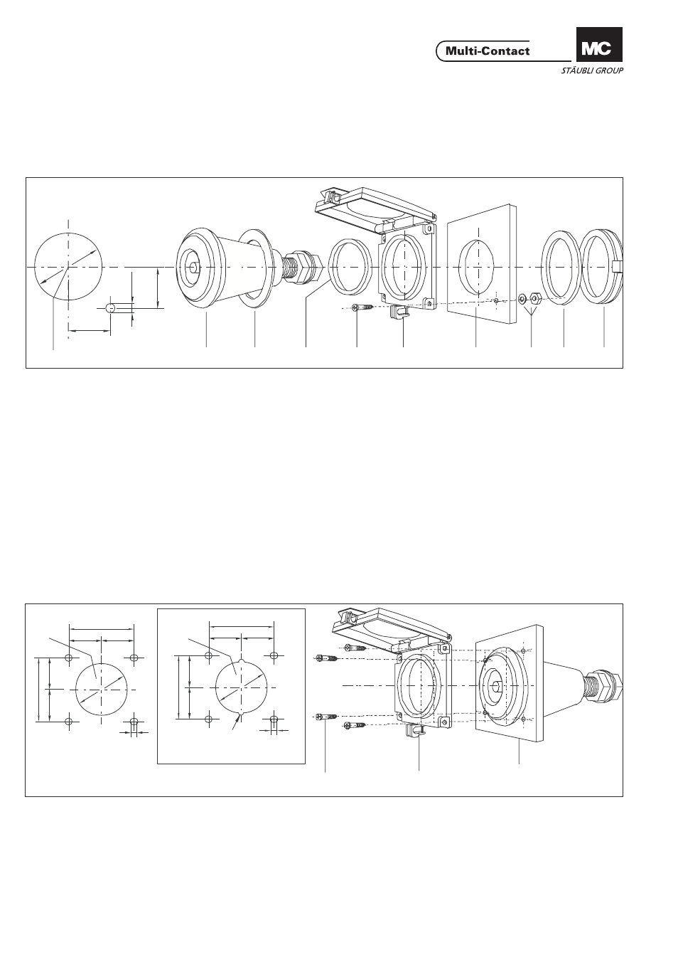
Variante de montage No. 1
Mounting way Nr. 1
Le couvercle se monte entre le panneau et l‘embase avec une
bague d‘adaptation. Une vise est préconisée pour assurer le
blocage en rotation. (Non valide pour ID-S10BV-C...)
Mounted together with the ring nut of the receptacle with the
corresponding adapter ring and an anti-rotation screw (not
valid for ID/S10BV-C...)
1. Cote d, voir Tab. 1, page 3 / 8
2. Prise à encastrer
3. Bague d‘étanchéité
4. Bague d‘adaptation
5. Vis M3
6. Couvercle de protection
7. Panneau
8. Ecrou M3 + rondelle
9. Bague PUR
10. Ecrou cylindrique de la prise à encastrer
1. Size d, according to Tab. 1, page 3 / 8
2. Receptacle
3. Flat sealing
4. Adapter ring
5. Screw M3
6. Protective cover
7. Front panel
8. Nut M3 + washer
9. PUR-ring
10. Ring nut of the receptacle
Variante de montage No. 2
(pour ID/...16BV-NS..., ID/S10BV-C...)
Mounting way Nr. 2
(for ID/...16BV-NS..., ID/S10BV-C...)
Fixation avec 4 vis auto-taraudeuses. Le couvercle coiffe
l‘embase, montée préalablement sur le panneau. Une bague
d‘adaptation n‘est pas nécessaire.
Fixation with 4 self-cutting screws. It is possible to assemble
the protective cover subsequently. Adapter rings not required.
1. Cote d, voir Tab. 1 page 3 / 8
2. Vis M3 (auto-taraudeuse)
3. Couvercle de protection
4. Panneau avec prise à encastrer
1. Size d, accroding to Tab. 1, page 3 / 8
2. Self-cutting screws M3
3. Protective cover
4. Front panel with receptacle