Multi-Contact MA260 Manuel d'utilisation
Page 5
Advanced Contact Technology
www.multi-contact.com
5 / 8
16
14
15
17
13
(ill. 13)
4. Contrôlez le sertissage visuelle-
ment.
(ill. 13)
4. Visually check the crimp.
Remarque:
Pour l’utilisation des pinces à sertir,
voir MA251 sous www.multi-con-
tact.com
Note:
to the operation of the crimping
pliers, see MA251, www.multi-
contact.com
Contrôle de l‘assemblage
Assembly control
(ill. 14)
Introduisez le contact serti par l’arrière
dans l’isolation de fi che ou de douille
jusqu’à l’enclenchement. Exercez
une légère traction sur le câble pour
contrôler que la pièce métallique est
bien enclenchée.
(ill. 14)
Insert the crimped-on contact into the
insulator of the male or female coupler
until it clicks into place. Pull gently on
the lead to check that the metal part is
correctly engaged.
(ill. 15)
Enfi chez la fi che de test par le côté
correspondant dans la douille ou la
fi che jusqu’en butée. Si le contact est
monté correctement, le marquage
blanc sur la fi che de test est encore
visible.
(ill. 15)
Insert the appropriate end of the test
pin into the male or female coupler as
far as it will go. If the contact is cor-
rectly located, the white mark on the
test pin must still be visible.
(ill. 16)
Serrez à la main le presse-étoupe à
l’aide des outils PV-MS
ou
(ill. 16)
Screw up the cable gland hand-tight
with the tools PV-MS
or
(ill. 17)
Serrez le presse-étoupe à l’aide des
outils PVWZ-AD/GWD et PVSSE-AD4.
(ill. 17)
Tighten the cable gland with the tools
PVWZ-AD/GWD and PVSSE-AD4.
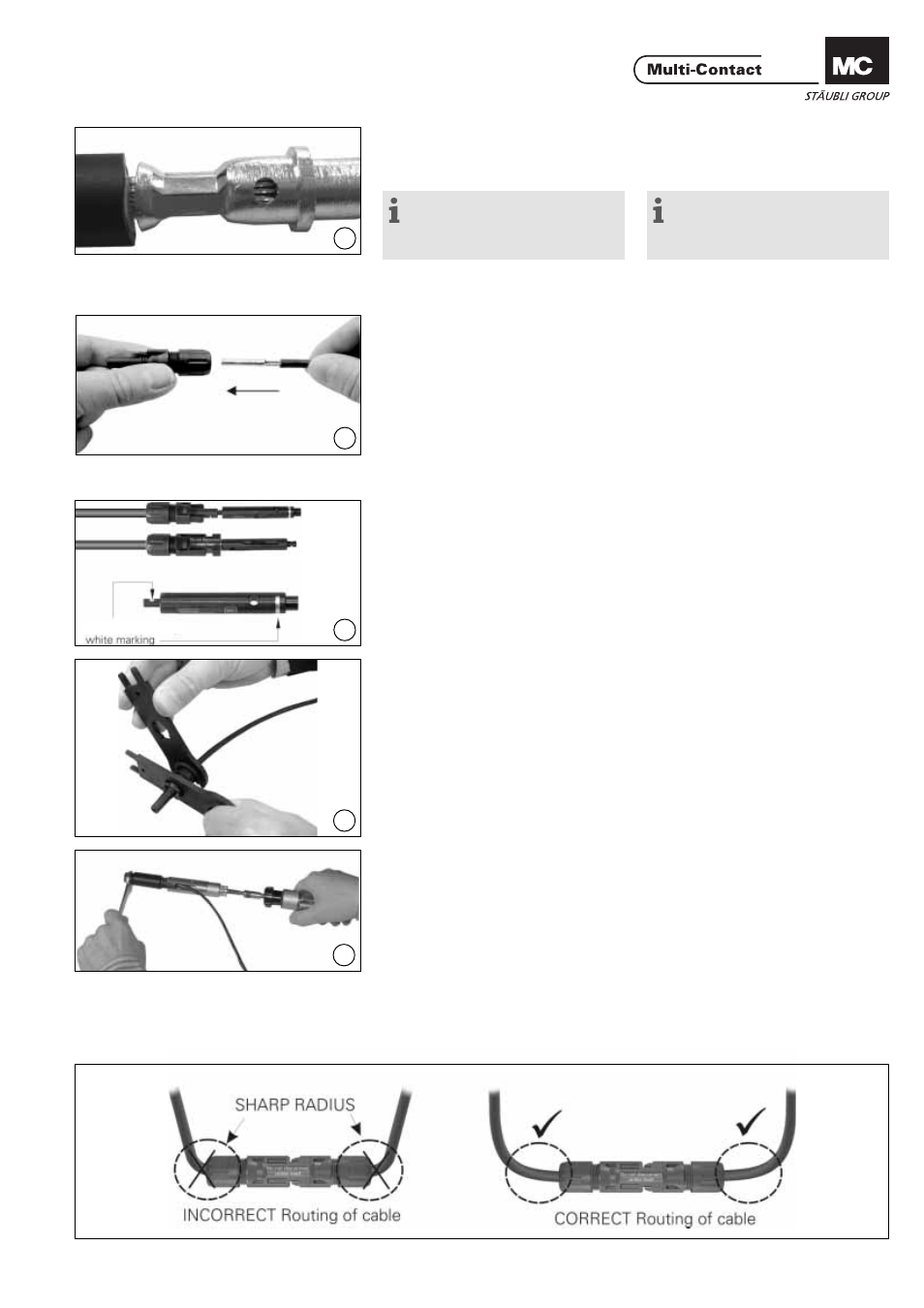
Disposition du câble
Cable routing
Se référer aux spécifi cations du
fabricant de câble pour un rayon de
courbure minimal.
Refer to cable manufactures specifi ca-
ton for minimum bending radius.
marquage blanc