Multi-Contact MA018 Manuel d'utilisation
Page 4
Advanced Contact Technology
8
7
Fabricant/Producer:
Multi-Contact AG
Stockbrunnenrain 8
CH – 4123 Allschwil
Tel.
+41/61/306 55 55
Fax
+41/61/306 55 56
www.multi-contact.com
© b
y
Multi-Contact A
G, Switz
erland – MA018 – 06.2013, Inde
x f
, Global Communications – Modi
fi
cations sous réserv
e / Subject to alterations
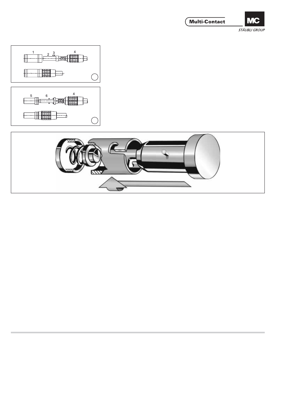
Montage douille
Socket assembly
(ill. 7)
Monter la goupille 3 sur la douille 2.
Engager l‘isolant avant 1 sur la douille
(la goupille 3 doit bloquer l‘isolant en
rotation) puis monter l‘isolant arrière 4.
(ill. 7)
Lay the anti-twist pin 3 in the keyway
of socket insert 2, align with the key-
way in the front insulation 1 and screw
tightly by hand into the back insulation 4.
Montage broche
Plug assembly
(ill. 8)
Assembler les isolants 4, 5 et la
broche 6 par vissage manuel.
(ill. 8)
Screw, by hand, the front insulation 5
together with the plug pin 6 and back
insulation 4.
Principe du verrouillage
baïonnette (Système-BV)
Bayonet locking system
(BV-System)
Phase d‘embrochage:
Aligner les marquages (point rouge,
ligne ou triangle blanc) rapportés sur
la douille et la broche. Connecter les
deux parties jusqu‘en butée, puis
pousser axialement tout en imprimant
à l‘une des deux parties un mouve-
ment de rotation relatif de 90° vers
la gauche ou la droite. Relâcher. La
connexion doit alors être verrouillée.
Plugging procedure:
The markings (red point, line or white
triangle) on the plug and socket have
to be lined up. Mate plug with socket
to the stop then insert further with
axial pressure and turn simultaneously
through 90° to the right or left until
the bayonet lock engages.
Phase de débrochage:
Pousser l‘une des deux parties dans
l‘axe, tout en lui imprimant un mou-
vement de rotation de 90° vers la
gauche ou la droite, de sorte à aligner
les marquages (point rouge, ligne ou
triangle blanc), apposés sur les deux
parties sur un même axe. Retirer la
broche de la douille.
Unplugging procedure:
Push plug in further and turn simul-
taneously through 90° to right or left
until the markings (red point, line or
white triangle) are lined up. Pull plug
out of socket.
Avis:
Pendant l’installation et les phases
d’embrochage ou débrochage, l’élé-
ment à raccorder ne doit pas être sous
charge! La protection contre les chocs
électriques doit être assurée par le
produit fi nal, à l’état monté.
Note:
During installation, connecting or
disconnecting, the terminal must not
be connected under load! Protection
against electric shock has to be pro-
vided in the enduse product.