Thru-the-wall installation continued – Friedrich Kuhl Series 6000 BTU Window Air Conditioner Installation and Operation Manual Manuel d'utilisation
Page 35
34
35
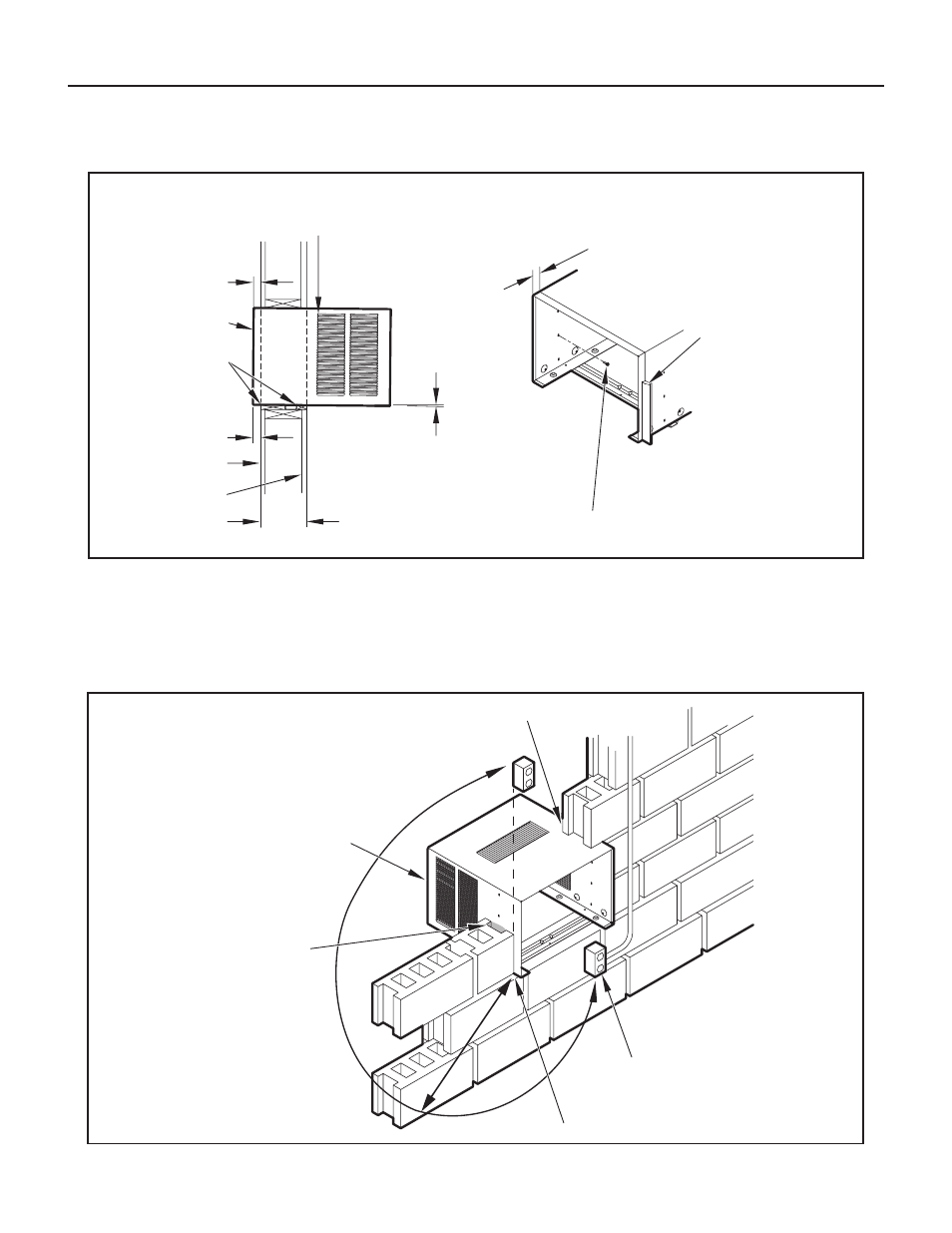
Figure 72
Figure 71
Thru-the-Wall Installation continued
STEP 7.
Cut two pieces of standard 1" lumber (supplied by installer)
to the length and width required. Place in front and back of
bottom sill channel as shown in Figure 71. Secure with nails
(supplied by installer).
STEP 8.
Seal all holes in the sleeve with caulking compound (supplied
by installer).
SOLID MASONRY CONSTRUCTION
STEP 9.
Complete the installation by following Steps 5.3 through 7 of
Standard Window Installation (Pages 30, 31). Window seal
gasket mentioned in Step 6 will not be required.
IMPORTANT:
Before operating your unit, read
CIRCUIT PROTECTION
of Standard Window Instructions under Step 7 (Page 31).
3
/
4
" MINIMUM
SLEEVE FRONT
1" THICK LUMBER
FRONT EDGE OF LOUVERS
MUST ALWAYS BE OUTSIDE OF
EXTERIOR WALL SURFACE
1" MINIMUM
INSIDE WALL
EXTERIOR WALL
MAX. WALL THICKNESS
ALLOWED 8
1
/
2
"
1
/
4
" SLOPE DOWN.
POSITION AND SECURE
SLEEVE DOWNWARD.
SLOPE OUTSIDE FOR
DRAINAGE.
1
1
/
2
" SCREWS (F IN PARTS LIST) / 3 EA. SIDE
NAILS MAY BE USED IF DESIRED.
3
/
4
" MINIMUM FRONT
EDGE OF SLEEVE TO
INSIDE WALL SURFACE.
TRIM AROUND THE
SLEEVE WITH A
SUITABLE WOOD
MOULDING AND
FINISH TO SUIT.
CAULK ALL AROUND
SLEEVE ON OUTSIDE
TO INSURE A WEATHER
TIGHT SEAL.
FRR092
CAULK ALL SIDES
CABINET
MORTAR
NOTE:
ELECTRICAL RECEPTACLE LOCATION
FROM POINT “X” MUST BE WITHIN A MAXIMUM
RADIUS OF 69" FOR 115V UNITS.
ELECTRICAL
RECEPTACLE
POINT “X”
FRR093