Kichler 15165 Manuel d'utilisation
Luminaires Kichler
FOR USE WITH LANDSCAPE LIGHTING SYSTEMS ONLY.
1) The device is accepted as a component of a landscape lighting system
where the suitability of the CSA or UL labeled combination shall be deter
mined by CSA, UL respectively or the local inspection authorities having
jurisdiction.
2) Fixture shall be connected to an extra low voltage transformer approved for
use with landscape lighting systems.
3) This fixture is to be connected to a secondary wiring of the following type:
12 GA 60°C minimum type;
SPT-3 suitable for outdoor use; or
approved landscape lighting cable.
Date Issued: 12/2/11
IS-15165-CB
OUTDOOR USE ONLY
DOM ETRE INSTALLE A L’EXTERIEUR
INSTRUCTIONS
For Assembling and Installing Fixtures in Canada
Pour L’assemblage et L’installation Au Canada
For warranty information please visit: http://www.landscapelighting.com/portal/warranty_page
Pour de plus amples informations sur la garantie, cliquez sur le lien ci-dessous : http://www.landscapelighting.com/portal/warranty_page
QUIC DISC
™
WIRING INSTRUCTIONS
Turn off power.
The full length of the 18 GA fixture wire may be used to connect with the 10 GA or 12 GA cable provided the following conditions are met:
• Wiring is to be protected by routing close to the fixture or accessory or secured to a building structure such as house or deck.
• 18 GA fixture wiring is to be cut off so that it is attached to the connector within 6 inches of the fixture or building structure.
• If it is necessary to make the connections underground, then no more than 6 inches of the 18 GA fixture wire is to be buried.
The Quic Disc
™
connector is designed to install one fixture and accommodates one 18 GA fixture wire and one 10 GA or one 12 GA supply wire.
Place the 10 gauge supply wire across the area marked 10 GA on Quic Disc
™
or place the 12 gauge supply wire across the area marked 12 GA
on Quic Disc
™
.
Place the 18 gauge fixture wire across the area marked 18 GA on the Quic Disc
™
. After the wires are in place, connecta the top of the Quic
Disc
™
to the base with supplied screw, making sure that the wires remain flat in the bottom portion of the Quic Disc
™
, and the screw is tightened
all the way down.
The copper contacts will automatically pierce the wires’ insulation. Excess 18 GA fixture wire that sticks out the end of the Quic Disc
™
is to be cut off.
Make no other wiring connections to the 18 GA fixture wire.
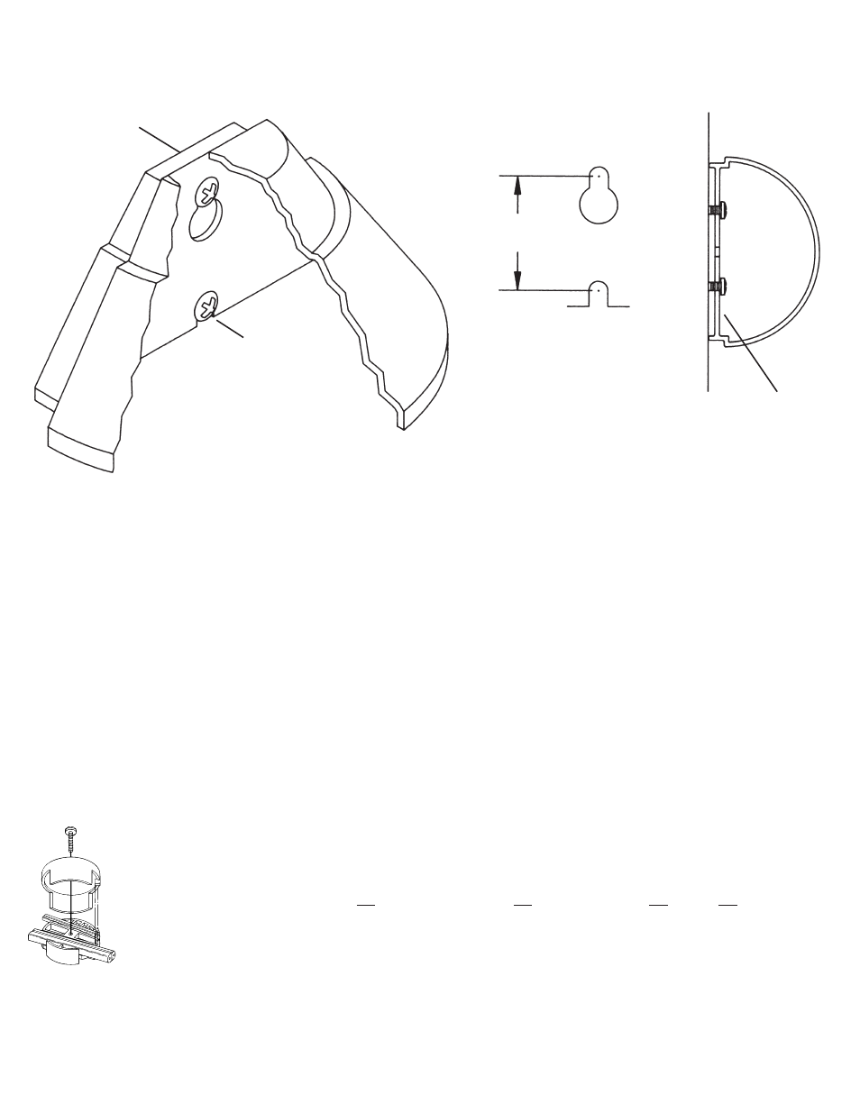
1) Establish center of post or a center line on mounting surface.
2) Drill two 1/8” (3mm) pilot holes into mounting surface on center line. Fig. 1
can be used as a template.
3) Using bottom inside edge of fixture as a depth gage, drive screws into
pilot holes until bottom of screw heads almost touch bottom inside edge of
fixture. See fig. 2.
4) Slide slot at bottom of fixture over bottom screw.
5) Slip large portion of keyhole over top screw.
6) Push fixture down so top screw is in smaller portion of keyhole.
7) Secure in place by tightening screws.
FIXTURE
ÉLÉMENT
SCREW
VIS
BOTTOM INSIDE EDGE
BORD DU FOND
INTERIEUR
SLOT
FENTE
KEYHOLE
TROU DE SERRURE
1 1/8”
(29MM)
FIGURE 1
FIGURE 2