Paso 5 - determine el método de ventilación, Importante, Nota – haier 24 Inch Over-the-Range Microwave Installation Guide Manuel d'utilisation
Page 67
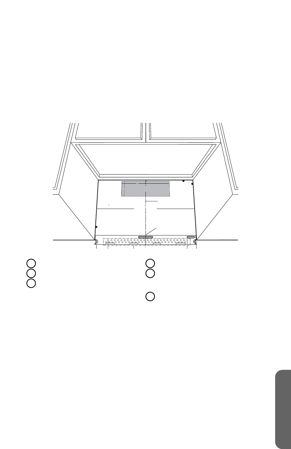
4. Marque la pared a través de los orificios A y B.
IMPORTANTE:
Si ninguno de los orificios A o B quedan alineados con un
pie derecho, localícelo dentro del área de la placa de montaje y marque un
tercer orificio para que quede alineado con el pie derecho.
5. Taladre un orificio en los orificios A y B.
NOTA:
Se debe utilizar un tornillo para madera cuando se instala en un pie
de madera.
•
Taladre un orificio de ⁵⁄₈" (15,9 mm) para utilizar un perno de ajuste.
•
Taladre un orificio de ³⁄₁₆" (4,8 mm) para utilizar un tornillo para madera.
6. Quite la plantilla de la placa de montaje/pared trasera y colóquela a un lado. NO
COLOQUE LA PLACA EN ESTE MOMENTO.
3/8" TO EDGE
24” MINIMUM WIDTH REQUIRED
REAR WALL TEMPLATE
NOTE: IT IS VERY IMPORTANT TO
READ AND FOLLOW THE DIRECTIONS
IN THE INSTALLATION INSTRUCTIONS
BEFORE PROCEEDING WITH THIS
REAR WALL TEMPLATE.
This Rear Wall Template serves to position the bottom
mounting plate and to locate the horizontal exhaust
outlet.
1. Use a level to check that the template is positioned
accurately.
2. Locate and mark at least one stud on the left or
right side of the centerline.
It is important to use at least one wood
screw mounted firmly in a stud to support the weight
of the microwave. Mark two additional, evenly spaced
locations for the supplied toggle bolts.
3. Drill holes in the marked locations. Where there is
a stud, drill a 3/16" hole for wood screws. For holes
that do not line up with a stud, drill 5/8" holes for
toggle bolts.
DO NOT INSTALL THE MOUNTING PLATE
AT THIS TIME.
4. Remove the template from the rear wall.
5. Review the Installation Instruction book for your
installation situation.
Locate and mark holes to align with holes in the
mounting plate.
IMPORTANT:
LOCATE AT LEAST ONE STUD ON EITHER SIDE OF
THE CENTERLINE.
MARK THE LOCATION FOR 2 ADDITIONAL, EVENLY
SPACED TOGGLE BOLTS IN THE MOUNTING PLATE
AREA.
Locate and mark holes to align with holes in the
mounting plate.
IMPORTANT:
LOCATE AT LEAST ONE STUD ON EITHER SIDE OF
THE CENTERLINE.
MARK THE LOCATION FOR 2 ADDITIONAL, EVENLY
SPACED TOGGLE BOLTS IN THE MOUNTING PLATE
AREA.
Trim the rear wall template along the dotted line.
Trim the rear wall template along the dotted line.
F. CUT OUT FOR HORIZONTAL
OUTSIDE EXHAUST
12"
4"
Darle vuelta a la hoja para consultar la
versión en Espa ol.
e
e
f
a
b
d
c
A
Orificio A
B
Orificio B
C
Trace una línea vertical sobre la
pared desde el centro del armario
superior.
D
Muescas de la línea central
E
Trace una línea horizontal en la pared
desde la parte inferior de la “Plantilla
de la pared trasera”.
F
Área de la placa de montaje
PASO 5 - DETERMINE EL MÉTODO DE VENTILACIÓN
IMPORTANTE:
Este horno de microondas se envía ensamblado para la
instalación de ventilación por recirculación de aire; sin embargo, está diseñado
para adaptarse a los siguientes métodos de ventilación. Seleccione el método
de ventilación requerido para su instalación y siga las instrucciones específicas
de su método:
65
ESP
AÑOL