Estilo 2 - debajo del armario empotrado, con marco, Importante, Alínea central – haier 24 Inch Over-the-Range Microwave Installation Guide Manuel d'utilisation
Page 65
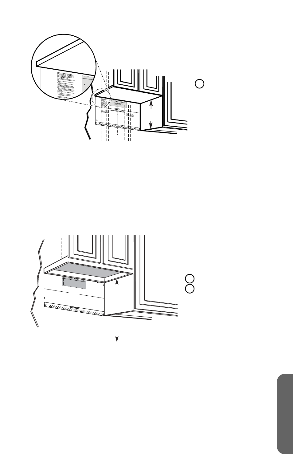
16½"
(41.9 cm)
a
A
Línea
central
ESTILO 2 - DEBAJO DEL ARMARIO EMPOTRADO, CON MARCO
IMPORTANTE:
El horno de microondas debe estar nivelado. Utilice un nivel de
carpintero para asegurarse de que la parte inferior del armario esté nivelada.
1. Trace una línea vertical sobre la pared en el centro del espacio cuyo ancho es de
24" (61 cm).
2. Coloque en la pared la plantilla de la placa de montaje/pared trasera de manera
que la línea central de la plantilla quede alineada con la línea central, y la parte
superior de la plantilla esté en contacto con la parte inferior del armario. Pegue
la plantilla en esta posición.
a
3/8" TO EDGE
NOTE: IT IS
VERY IMP
ORTANT T
O
READ AND
FOLLOW
THE DIRECT
IONS
IN THE INSTAL
LATION
INSTRUCT
IONS
BEFORE
PROCEED
ING WITH TH
IS
REAR WA
LL TEMP
LATE.
This Rear Wa
ll Template se
rves to positi
on the botto
m
mounting p
late and to locat
e the horizon
tal exhaust
outlet.
1. Use a leve
l to check t
hat the temp
late is position
ed
accurately.
2. Locate and
mark at least o
ne stud on t
he left or
right side of
the centerlin
e.
It is important
to use at lea
st one wood
screw mounte
d firmly in a s
tud to suppo
rt the weigh
t
of the microw
ave. Mark tw
o additional,
evenly sp
aced
locations for
the supplied
toggle bolts
.
3. Drill holes
in the marked
locations. Wh
ere there is
a stud, dri
ll a 3/16" hole
for wood scr
ews. For hole
s
that do no
t line up with
a stud, drill
5/8" holes fo
r
toggle bolts
.
DO NOT INS
TALL THE M
OUNTING P
LATE
AT THIS TIME
.
4. Remove th
e template fr
om the rear w
all.
5. Review the
Installation I
nstruction bo
ok for your
installation
situation.
Locate and
mark holes t
o align with
holes in the
mounting pl
ate.
IMPORTA
NT:
LOCATE A
T LEAST
ONE STUD
ON EITH
ER SIDE O
F
THE CENTER
LINE.
MARK THE L
OCATION
FOR 2 AD
DITIONAL
, EVENLY
SPACED TO
GGLE BO
LTS IN TH
E MOUNT
ING PLATE
AREA.
Locate an
d mark hole
s to align w
ith holes in t
he
mounting pl
ate.
IMPORTANT:
LOCATE A
T LEAST ON
E STUD
ON EITHE
R SIDE OF
THE CENT
ERLINE.
MARK TH
E LOCATI
ON FOR 2
ADDITION
AL, EVENL
Y
SPACE
D TOGGLE
BOLTS IN
THE MOU
NTING PLAT
E
AREA.
Trim the re
ar wall tem
plate along
the dotted
line.
Trim the re
ar wall temp
late along t
he dotted l
ine.
12"
4"
Darle vuelta
a la hoja pa
ra consultar
la
versión en E
spañol.
b
A
Línea central
B
30" (76,2 cm) hasta la
superficie de cocción
63
ESP
AÑOL