Analog Way XTD825 Manuel d'utilisation
Page 21
STUDIO SCAN XTD825 / 625™
Chapter 10 : RS-232 PROGRAMMER'S GUIDE (continued)
PAGE 21
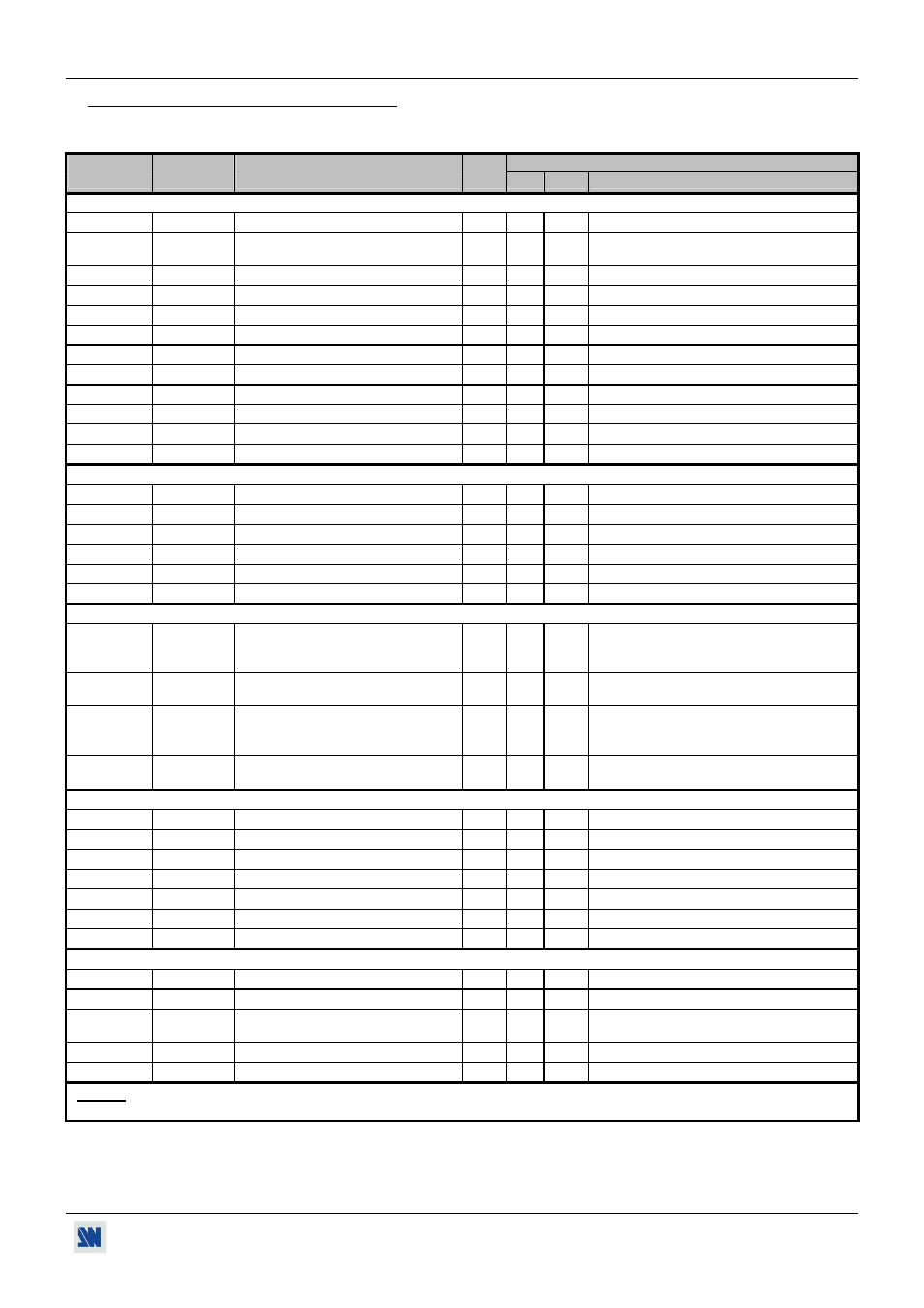
10-4. COMMANDS AND RESPONSES TABLE
The following table resumes commands which are recognized as valid and the responses that will be returned to the control
device (on RS-232 port).
ASCII
RESPONSE
COMMAND
TYPE
VALUE
COMMAND
DESCRIPTION
MIN MAX
DESCRIPTION
FRONT PANEL COMMANDS
z
FRZ
FREEZE.
Rd/Wr
0
1
0 = freeze inactive
1 = freeze active.
a
ASP
Size mode selection.
Rd/Wr
0
2
0 = underscan.
1 = overscan.
2 = ZOOM.
h
HP
Horizontal position adjustment.
Rd/Wr
0
255
v VP
Vertical
position
adjustment. Rd/Wr
0
255
w HW
Horizontal
size
adjustment. Rd/Wr
0
255
s
VS
Vertical size adjustment.
Rd/Wr
0
255
H
ZHP
Zoom horizontal position.
Rd/Wr
0
255
V
ZVP
Zoom vertical position.
Rd/Wr
0
255
W
ZHW
Zoom horizontal size.
Rd/Wr
0
255 0 = 100%
255 =200%
S
ZVS
Zoom vertical size.
Rd/Wr
0
255 0 = 100%
255 =200%
R
REC
RECALL.
Rd/Wr
0
1
1 = recall (automatic reset)
M
STO
STORE.
Rd/Wr
0
1
1 = store (automatic reset)
INPUT COMMANDS
*
D
RGBI
Input type
Rd/Wr
0
1
0 = analog
1 = DVI
GP
REFH
Genlock H phase adjustment
Rd/Wr
0
255
GS
REFS
Genlock subcarrier phase adjustment. Rd/Wr
0
65535
GL
GLD
Genlock load.
Rd/Wr
0
1
0 = Hi-Z
1 = 75 ohms.
E
SOGI
SOG input selection.
Rd/Wr
0
1
0 = no
1 = yes.
l
LOAD
H sync load selection.
Rd/Wr
0
1
0 = Hi-Z
1 = 75 ohms.
OUTPUT COMMANDS
F
OFMT
Output standard selection
Rd/Wr
0
7
0 = NTSC
1 = PAL
2 = NTSCj.
GR REFR
Synchronization
mode
selection. Rd/Wr
0
1
0
=
internal.
1 = genlock.
e
OSIG
RGB/YUV output selection.
Rd/Wr
0
2
0 = YUV.
1 = RGBS.
2 = RGsB.
P
OPAT
Test pattern selection.
Rd/Wr
0
1
0 = no test pattern.
1 = test pattern selected.
IMAGE
COMMANDS
f
FLK
Flicker level selection.
Rd/Wr
0
7
k
BLK
Black level adjustment
Rd/Wr
0
255
r
RLV
Red level adjustment.
Rd/Wr
0
127
g
GLV
Green
level
adjustment.
Rd/Wr
0
127
b
BLV
Bleu level adjustment.
Rd/Wr
0
127
L
HSMT
Horizontal smooth
Rd/Wr
0
1
0 = OFF
1 = ON.
yp
PRES
PRESET
Rd/Wr
0
1
1 = PRESET (automatic reset).
CONTROLS
COMMANDS
yl
LOCK
Front panel locking selection.
Rd/Wr
0
1
0 = unlocks all buttons. 1 = locks all buttons.
yc
EPOS
Erase memory.
Rd/Wr
0
1
1 = erase all memories (automatic reset).
Y
FRES
Default value.
Rd/Wr
0
1
1 = set all the parameters to the default value
(automatic reset).
xu VERU
Device
version
Rd
0
65535 Example: 104 = Version 1.4
xi
I_
Identification
number.
Rd
0
65535 Value displayed in hexadecimal in the device.
NOTE: * = available with the optional DVI input only.
Rd = Read only command.
Rd/Wr = Read and write command.