Schéma de connectique, Cvm-c10 manuel d’instructions, Power supply v – CIRCUTOR CVM-C10 Series Manuel d'utilisation
Page 12: Nl1 l2 l3 n
Advertising
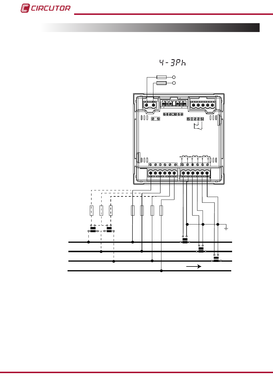
3.4.- SCHÉMA DE CONNECTIQUE
3.4.1.- Mesure de Réseau triphasé avec connexion à 4 fils, modèles CVM-C10-ITF et
CVM-C10-mV
Système de mesure :
Power
Supply
V
L1
V
L2
V
L3
N
L1
L2
L3
N
POWER SUPPLY
INPUTS
A
(+) B(-)
GND
RS485
S1
S2
S1
S2 S1
S2
L1
P1
P2
L2
L3
300V ~
Ph-N
Ph-Ph
520V ~
N
V
L3
L2
V
L1
V
P1
P2 P1
P2
I1 I2
OUTPUTS
Rc R2 R1
Tc T2 T1
S0- S0+ S0+
V
L1
V
L2
V
L3
a
b
A
B
a
b
A
B
S1
S2
P1
P2
S1
S2
P1
P2
S1
S2
P1
P2
LOAD
Figure 3: Mesure triphasée avec connexion à 4 fils, modèles CVM-C10-ITF et CVM-C10-mV.
12
CVM-C10
Manuel d’instructions
Advertising