KITCHENAID 36 Inch Gas Cooktop Owner's Manual Manuel d'utilisation
Page 15
15
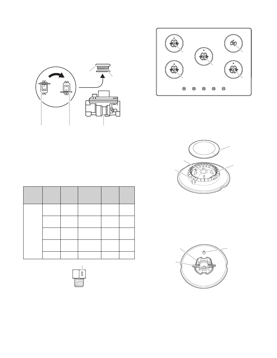
Style 2:
The cap does not have a slot and requires a wrench
to be removed.
Remove the access cap by using a wrench, turning the
access cap counterclockwise.
Remove spring retainer from the cap by pushing against the
flat side of the spring retainer. Look at the spring retainer to
locate the “LP” or “NAT” position. Turn over the spring retainer
so the “NAT” is showing on the bottom. Snap the spring
retainer back into the cap. Reinstall the cap onto the regulator.
A
B
C
D
E
A.
Access cap
B.
Gasket
C.
Gas pressure
regulator
D. NAT position
E. LP position
4.
For more information regarding gas installation requirements
see the Gas Supply Requirements section of your Owner’s
Manual.
5.
If they are installed, remove the burner grates.
Use the following chart to match the correct gas orifice spud
with the burner location and model being converted.
Natural Gas Orifice Spud Chart
Model
Family
Burner
Burner
Rating
(BTU)
Color
Stamp
(A)
Size
(mm)
KCG-
G530P,
KCG-
G536P
Right
Front
15000
WHITE
170
1.70
Left
Front
9100
BROWN
130
1.30
Right
Rear
5000
GREEN
96
0.96
Left
Rear
9100
BROWN
130
1.30
Center
18000
BLACK
188
1.88
A
A.
Stamp
Burner locations
A
B
D
C
E
A.
Left front
B.
Left rear
C.
Center
D. Right rear
E. Right front
6.
Remove burner cap.
7.
Using a T20
®
TORX
®
screwdriver, remove the burner base.
NOTE:
Remove one burner base at a time and then replace
after converting. Do not disassemble entire cooktop.
B
D
C
A
A.
Igniter electrode
B.
Gas tube
opening
C. Burner cap
D. Burner base
8.
Apply masking tape to the end of a 7 mm nut driver to help
hold the gas orifice spud in the nut driver while changing it.
Press nut driver down onto the gas orifice spud and remove
by turning it counterclockwise and lifting out. Set gas orifice
spud aside.
A
B
C
A.
Orifice spud
B.
Orifice spud holder
C.
Spark electrode