KITCHENAID 36 Inch Gas Cooktop Owner's Manual Manuel d'utilisation
Page 13
13
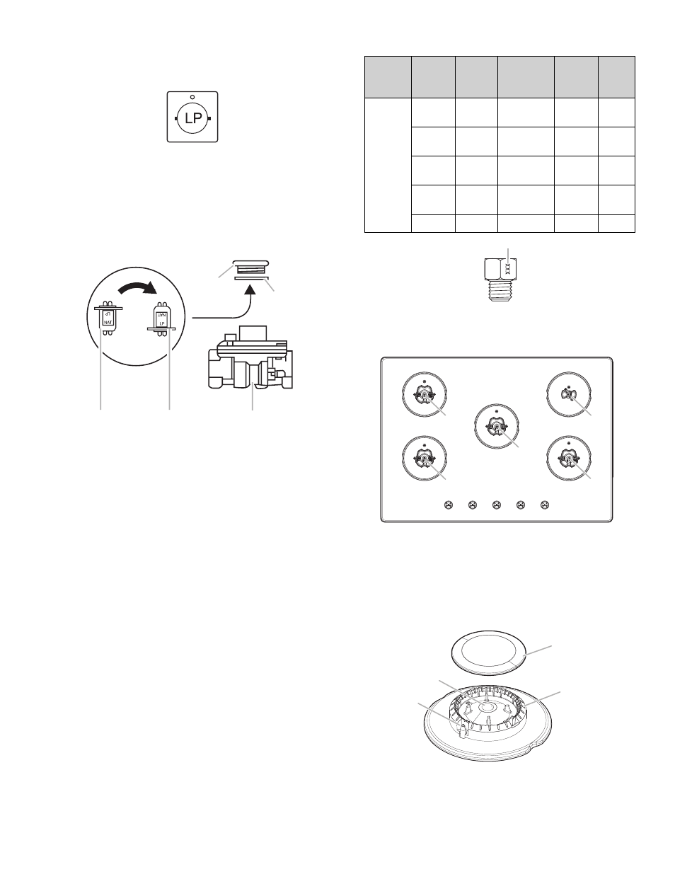
The gas pressure regulator has two settings that are stamped
on either side of the cap. Turn the cap and reinstall into
regulator with the stamp “LP” visible from the outside of the
regulator.
Style 2:
The cap does not have a slot and requires a wrench
to be removed.
Remove the access cap by using a wrench, turning the
access cap counterclockwise.
Remove the spring retainer from the cap by pushing against
the flat side of the spring retainer. Look at the spring retainer
to locate the “NAT” or “LP” position. Turn over the spring
retainer so the “LP” is showing on the bottom. Snap the spring
retainer back into the cap. Reinstall the cap onto the regulator.
A
B
C
D
E
A.
Access cap
B.
Gasket
C.
Gas pressure
regulator
D. LP position
E. NAT position
4.
Test the gas pressure regulator and gas supply line.
The regulator must be checked at a minimum 2.5 cm water
column above the set pressure. The inlet pressure to the
regulator should be as follows for operation and checking the
regulator setting:
Propane Gas:
Minimum pressure: 10" (25.4 cm) WCP, 2.49 kPa (0.36 psi)
Supply pressure: 14" (35.56 cm) WCP, 3.5 kPa (0.50 psi)
Gas Supply Pressure Testing
Line pressure testing above 1/2 psi (3.5 kPa) gauge 14"
(35.5 cm) WCP
The cooktop and its individual shut-off valve must be
disconnected from the gas supply piping system during any
pressure testing of that system at test pressures in excess of
1/2 psi (3.5 kPa).
Line pressure testing at 1/2 psi (3.5 kPa) gauge 14"
(35.5 cm) WCP or lower
The cooktop must be isolated from the gas supply piping
system by closing its individual manual shut-off valve during
any pressure testing of the gas supply piping system at test
pressures equal to or less than 1/2 psi (3.5 kPa).
5.
If they are installed, remove the burner grates.
Use the following chart to match the correct gas orifice spud
with the burner location and model being converted.
Propane Gas Orifice Spud Chart
Model
Family
Burner
Burner
Rating
(BTU)
Color
Stamp
(A)
Size
(mm)
KCG-
G530P,
KCG-
G536P
Right
Front
11000
GREEN
100
1
Left
Front
9000
YELLOW
90
0.9
Right
Rear
4000
RED
60
0.6
Left
Rear
9000
YELLOW
90
0.9
Center
11000
GREEN
100
1
A
A.
Stamp
Burner Locations
A
B
D
C
E
A.
Left front
B.
Left rear
C.
Center
D. Right rear
E. Right front
6.
Remove all burner caps and burner bases.
7.
Using a T20
®
TORX
®
screwdriver, remove the burner base.
NOTE:
Remove one burner base at a time, and then replace after
converting. Do not disassemble entire cooktop.
B
D
C
A
A.
Igniter electrode
B.
Gas tube opening
C.
Burner cap
D.
Burner base