Multi-Contact MA101 Manuel d'utilisation
Page 3
Advanced Contact Technology
www.multi-contact.com
3 / 4
1
6
x
x
6
b
7
6
c
7
MC
2
6
5
MC
3
6
90°
c
7
MC
4
5
1
MC
5
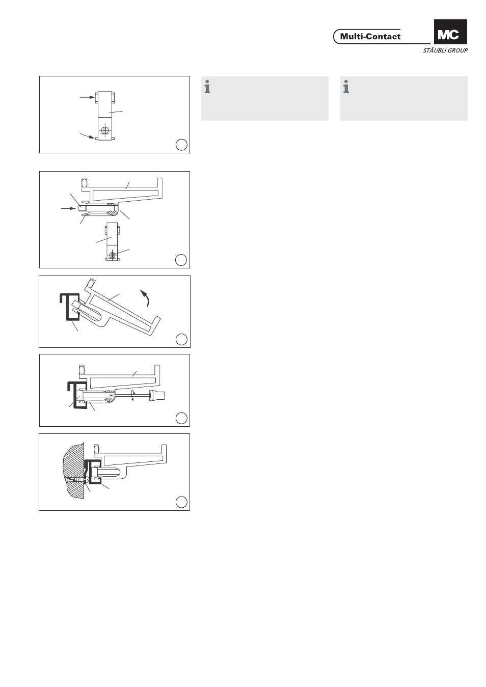
Hinweis:
Pour le rangement de cordons de
mesure 2 mm, il y a lieu de couper
d’un côté les deux ergots (x) des
supports (6) (ill. 1).
Note:
The two spacing bosses (x) from
plastic hooks (6) should be removed
from one side when using 2mm
laboratory leads (ill. 1).
Montage
Assembly
(ill. 2)
Monter la vis de fi xation (7) par l‘ar-
rière du support (6) dans le logement
(b).
L‘embout de la vis de fi xation (7) doit
être parallèle à la fourche (c).
(ill. 2)
Insert fi xing bolt (7) into hole (b) from
the rear of hook (6) ensuring that the
head of the fi xing bolt (7) is parallel to
the fork (c).
(ill. 3)
Incliner le support (6) de manière à an-
crer la partie inférieure de la fourche
dans le rail (5), puis le relever jusqu‘à
l‘encliquetage de la partie supérieure.
Placer le support (6) dans la position
souhaitée.
(ill. 3)
Insert the lower cross groove of hook
(6) into bracket holder (5) by tilting
and then turn to upright position till
top cross groove engages.
Slide hook (6) into desired position.
(ill. 4)
Pousser la vis de fi xation (7) en arrière.
Tourner la vis de fi xation de 90° pour
écarter la fourche (c).
(ill. 4)
Push the inserted fi xing bolt (7) to its
end position. To expand the fork (c),
turn the fi xing bolt (7) through 90°
with a screwdriwer.
(ill. 5)
Fixer le rail de fi xation (1) au mur
avec les vis jointes. Accrocher le rail
d‘ancrage (5) muni des supports (6) au
rail de fi xation (1).
(ill. 5)
Mount clamp rail (1) against wall with
the screws which are provided. Hang
the assembled fi xing rail (5) into clamp
rail (1).