Verify anti-tip bracket is installed and engaged – Maytag GY399LXUS Installation Manuel d'utilisation
Page 13
13
2. Attach terminal lugs to line 1 (black), bare (green) ground, and
line 2 (red) wires. Loosen (do not remove) the setscrew on the
front of the terminal lug and insert exposed wire end through
bottom of terminal lugs. Securely tighten setscrew to torque
as shown in the following Bare Wire Torque Specifications
chart.
Bare Wire Torque Specifications
Attaching terminal lugs to the terminal block - 20 lbs-in. (2.3 N-m)
3. Use
³⁄₈" nut driver to connect the bare (green) ground wire to
the center terminal block post with one of the 10-32 hex nuts.
4. Connect line 1 (black) and line 2 (red) wires to the outer
terminal block posts with 10-32 hex nuts.
5. Securely tighten hex nuts.
6. Replace terminal block access cover.
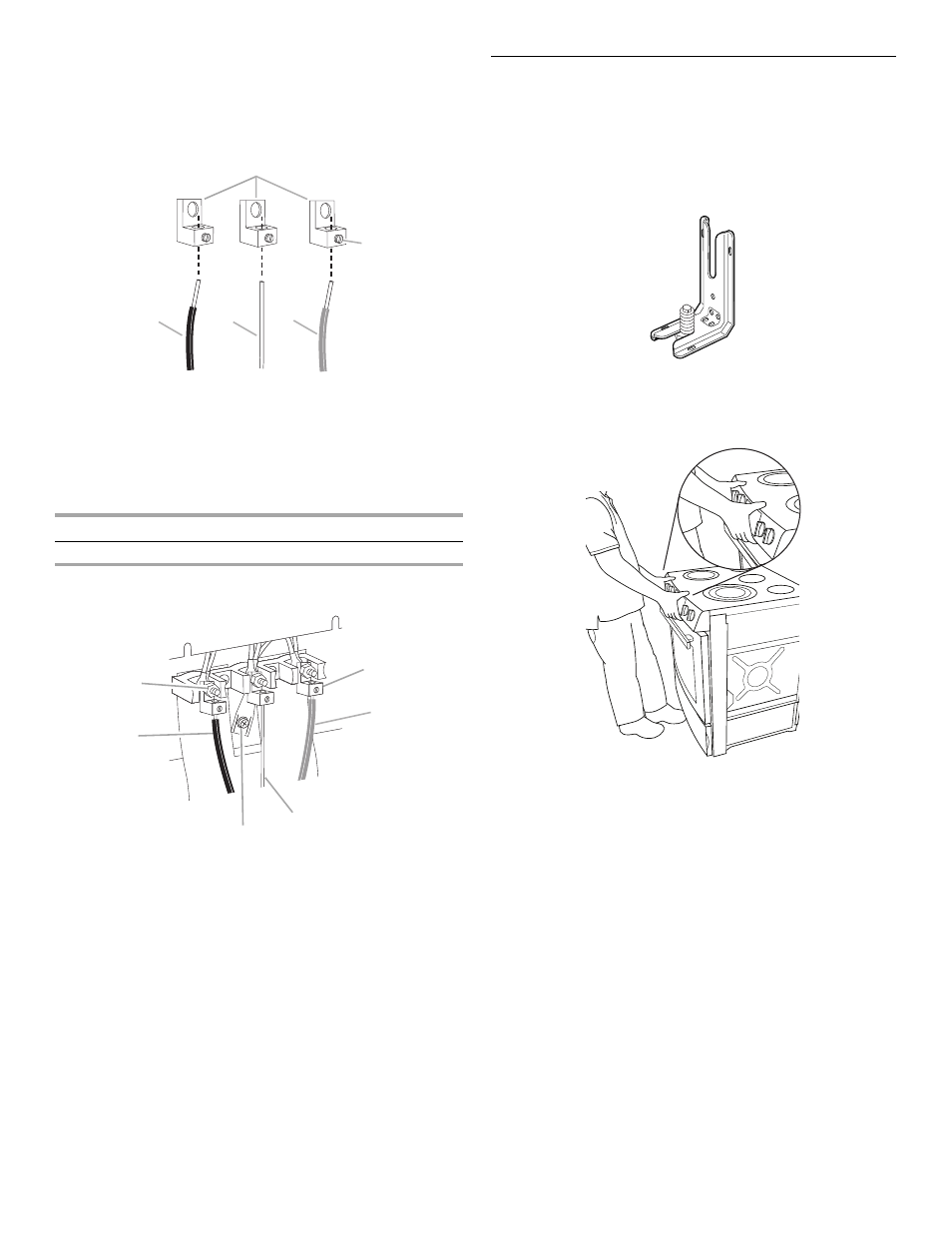
Verify Anti-Tip Bracket Is Installed and
Engaged
On models with a storage drawer:
1. Remove the storage drawer.
2. Use a flashlight to look underneath the bottom of the range.
3. Visually check that the rear range foot is inserted into the slot
of the anti-tip bracket.
On models with a warming drawer:
1. Place the outside of your foot against the bottom front of the
warming drawer to keep the range from moving, and grasp
the control panel with two hands as shown.
2. Slowly attempt to tilt the range forward.
If you encounter immediate resistance, the range foot is
engaged in the anti-tip bracket.
3. If the rear of the range lifts more than ½" (1.3 cm) off the floor
without resistance, stop tilting the range and lower it gently
back to the floor. The range foot is not engaged in the anti-tip
bracket.
IMPORTANT: If there is a snapping or popping sound when lifting
the range, the range may not be fully engaged in the bracket.
Check to see if there are obstructions keeping the range from
sliding to the wall or keeping the range foot from sliding into the
bracket. Verify that the bracket is held securely in place by the
mounting screws.
4. Slide the range forward, and verify that the anti-tip bracket is
securely attached to the floor or wall.
A. Terminal lug
B. Setscrew
C. Line 1 (black) wire
D. Bare (green) ground wire
E. Line 2 (red) wire
Wire Awg
Torque
8 gauge copper
25 lbs-in. (2.8 N-m)
6 gauge aluminum
35 lbs-in. (4.0 N-m)
A. 10-32 hex nut
B. Line 1 (black)
C. Ground-link screw
D. Bare (green) ground wire
E. Line 2 (red)
F. Terminal lug
A
B
C
D
E
B
F
A
E
D
C