Grass Valley DAC-1721 Manuel d'utilisation
Page 4
DAC-1721
Installation and Operation Manual
{NO SIGNAL DELAY}
NO SIGNAL DELAY
Signal absence is declared when the
signal level is lower than the signal
threshold during the selected period;
it can be adjusted from 0 to 255 s.
The default value is set to 15 s.
{SIGNAL THRESHOLD}
SIGNAL THRESHOLD
The presence signal threshold can be
adjusted from –72 to –48 dBFS by
6 dB steps. The default value is –60
dBFS.
{CONFIGURE ALARM}
It is possible to associate the STATUS Led color and/or GPI
relay activation to each detected error.
Alarm relay activation depends of the ENABLE selection of
the controller board menu GPI REPORT.
ALARM LEVEL
Associates to each error the STATUS led
color: GREEN, YELLOW, RED and
FLASH RED. This selection has no
influence on the {STATUS} menu display.
ALARM REPORT
The default value NONE is assigned to
errors. Alarm relay activation will be
associated to an error when GPI is set.
{FACTORY DEFAULT}
RESTORE Vxxx
Set the module with the factory default
parameters, indicates the current version
of the micro controller.
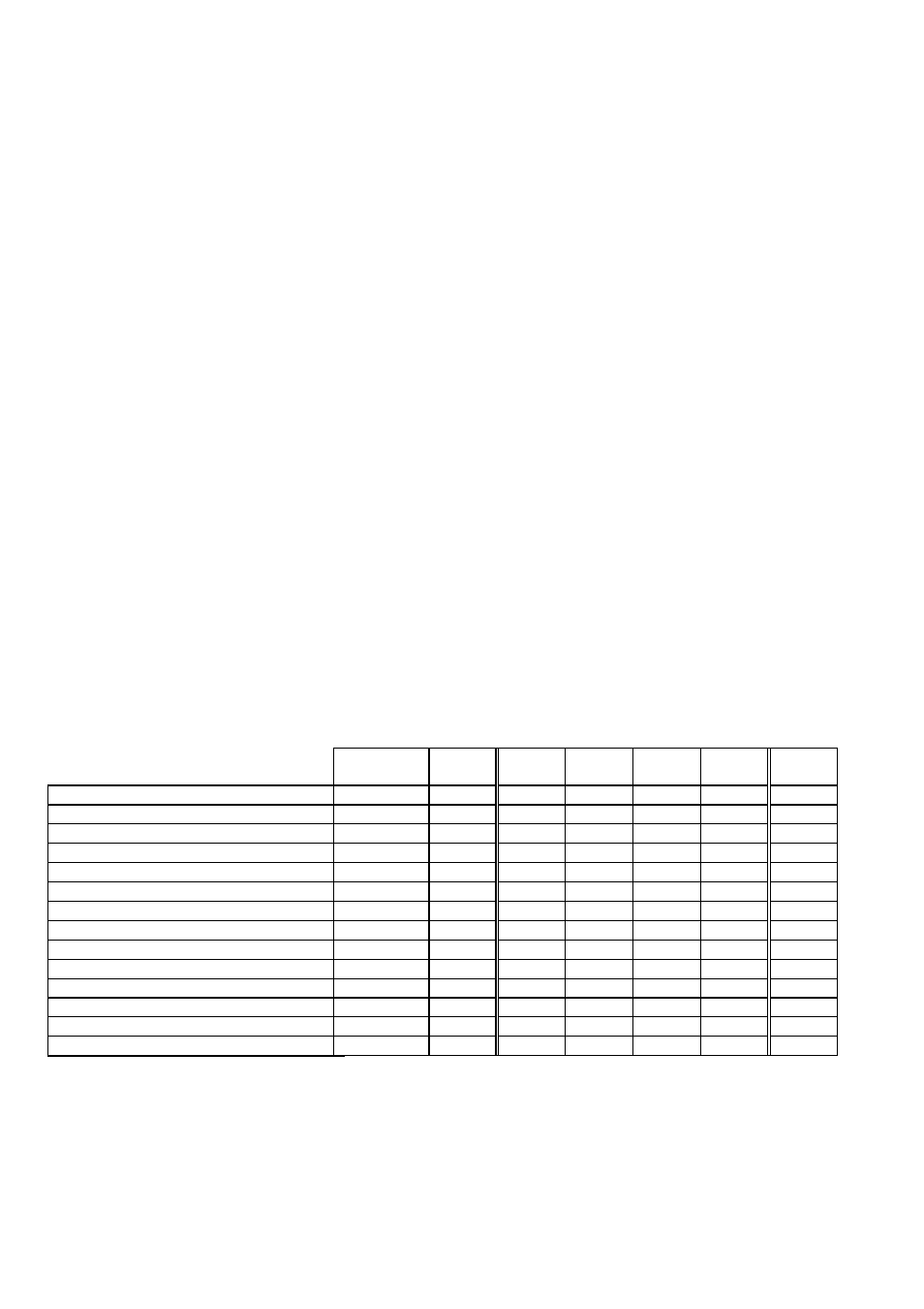
Status and Report
This table shows the front Led color and the report action according to the level of a given error condition. Notice that the
“Flashing Yellow” indicates that the SELECT button on the front panel has been pushed, and the card is being accessed via the
communication protocol
Serial
Report
GPI
Report
Green
Yellow
Red
Flashing
Red
Flashing
Yellow
NO LOCK
µ
µ
-
BIPHASE CODING
µ
µ
-
PARITY
µ
µ
-
CRCC ERROR
µ
µ
-
SLIPPED SAMPLE
µ
µ
-
CONFIDENCE
µ
µ
-
INVALID
µ
µ
-
NON AUDIO
µ
µ
-
NO SIGNAL
µ
µ
-
TONE
µ
µ
-
OVERLOAD
µ
µ
-
MUTE
µ
µ
-
Card accessed via the communication protocol
-
-
-
-
-
-
Yes
Rear Panel not matching
-
-
-
-
-
Yes
-
µ : Factory default.
Note: The non requested message affectation to an alarm status can only be accessed by the communication protocol (serial
port)